Coupling mechanism applied to electric vehicle wireless power transmission system

A technology of wireless power transmission and coupling mechanism, which is applied in the field of coupling mechanism, can solve the problems of reducing the coupling coefficient of the ground-side coil and the vehicle-side coil, the failure of normal transmission of electric energy, and affecting the efficiency of charging, so as to improve the coupling coefficient and anti-offset The effect of the characteristic

Inactive Publication Date: 2020-09-08
XUJI GRP +6
View PDF6 Cites 6 Cited by
  • Summary
  • Abstract
  • Description
  • Claims
  • Application Information

AI Technical Summary

Problems solved by technology

[0005] In the wireless power transmission system applied to electric vehicles, considering the practical application, the ground coil is fixed and buried below the ground; the vehicle coil is fixed at the bottom of the vehicle and the volume is limited, so it is difficult for the user to use the ground coil when parking. The center is completely aligned with the center of the car-side coil. When there is a deviation, the coupling coefficient between the ground-side coil and the car-side coil will be reduced, thereby affecting the charging efficiency; when the deviation is too large, the power cannot be transmitted normally, and the voltage of the ground-side coil will Excessively high jeopardizes the safety and stability of system operation

Method used


Image

  • Coupling mechanism applied to electric vehicle wireless power transmission system
  • Coupling mechanism applied to electric vehicle wireless power transmission system
  • Coupling mechanism applied to electric vehicle wireless power transmission system

Examples


Embodiment Construction

[0025] The present invention will be described in further detail below in conjunction with the accompanying drawings and specific embodiments, which are explanations of the present invention rather than limitations.

[0026] A coupling mechanism applied to a wireless power transmission system of an electric vehicle provided by the present invention includes:

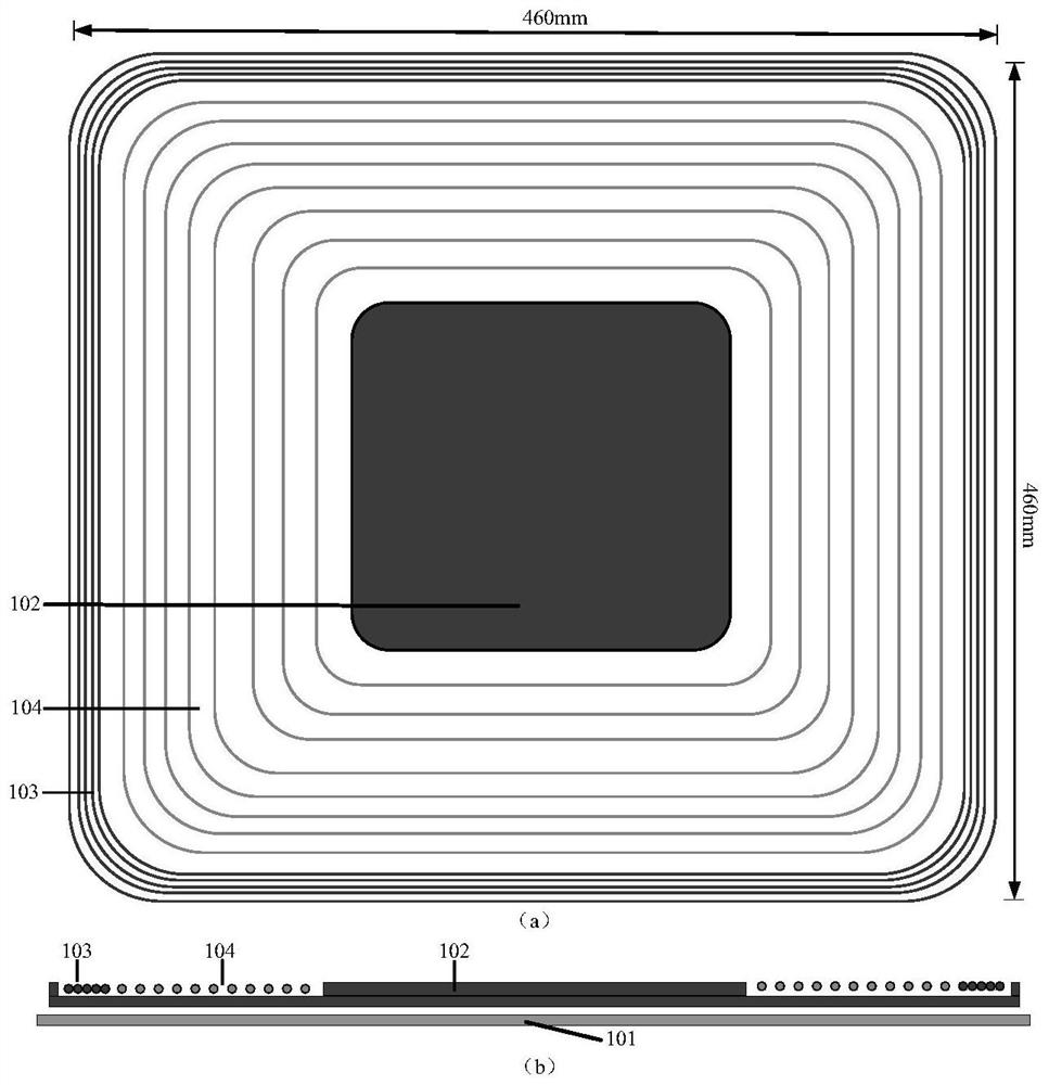
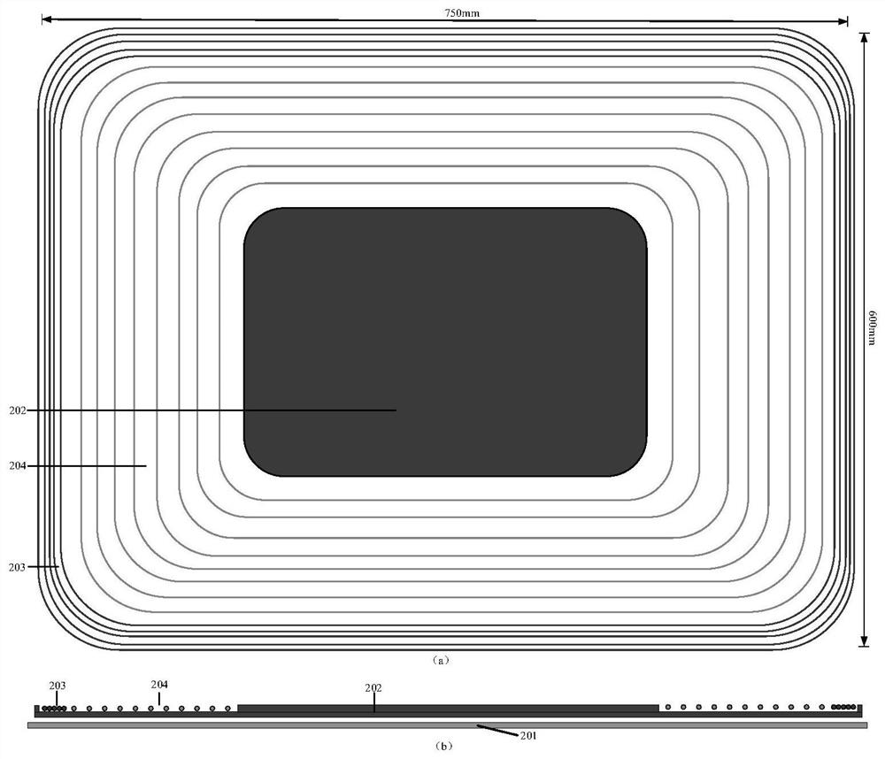
[0027] 1) Design the structure of the ground-end transmitting mechanism and the car-end picking mechanism of the coupling mechanism of the electric vehicle wireless power transmission system. The car-end picking mechanism is as follows: figure 1 As shown, the launch mechanism at the ground end is as figure 2 shown. 101 is an 8mm thick shielding aluminum plate for the chassis of the vehicle end, which is used as the shielding layer of the coupling mechanism; in order to reduce the loss of the coupling mechanism and provide a scientific and reasonable channel for the magnetic energy, 102 is a 1cm thick ferrite, which is ...


PUM

PropertyMeasurementUnit
thicknessaaaaaaaaaa
heightaaaaaaaaaa

Abstract

The invention discloses a coupling mechanism applied to an electric vehicle wireless power transmission system. The coupling mechanism comprises a ground end electric energy transmitting mechanism composed of an end rectangular transmitting coil, a ground end E-shaped ferrite and a ground end shielding aluminum plate, and a vehicle end electric energy receiving mechanism composed of a vehicle endsquare receiving coil, a vehicle end E-shaped ferrite and a vehicle end chassis shielding aluminum plate. An electric vehicle wireless power transmission system is constructed, circuit simulation parameters of the system are determined, and comparative analysis is performed on the coupling coefficient change and the Litz wire length of a traditional coupling mechanism under the offset condition. After being applied to an electric vehicle wireless power transmission system, the coupling coefficient between the two coils can be increased during normal work, the use of Litz wires of the coils isreduced, and the system loss is reduced; under the working condition that the coupling mechanism is not aligned, the anti-offset capability is enhanced, the safety and stability of the system are improved, normal work can still be ensured when the offset is large, and the safety and reliability of the wireless power transmission system are ensured.

Description

technical field [0001] The invention belongs to the technical field of wireless power transmission, and specifically relates to a coupling mechanism applied to a wireless power transmission system of an electric vehicle, so that it can meet the inductance and coupling coefficient required by the system, reduce the length of winding wires, and increase the misalignment of the coil center Under the anti-offset ability, improve the stability and safety of the system. Background technique [0002] Wireless power transmission is a safe and convenient power transmission method, which has the advantages of flexible and convenient use, less maintenance, strong environmental adaptability, and easy implementation. Magnetically coupled resonant wireless power transmission technology satisfies the requirements of distance, efficiency, power, and safety, and has broad application prospects in the fields of electric vehicles, consumer electronics, sensors, and implanted devices. [0003]...

Claims


Application Information

Patent Timeline
Patent Type & Authority Applications(China)
IPC IPC(8): H02J50/12H02J50/70H01F38/14B60L53/12
CPCB60L53/12H01F38/14H02J50/12H02J50/70Y02T10/70Y02T10/7072Y02T90/14Y02T90/16
Inventor 王林董晓帅陈枫吕双庆伍敏陈文洁
Owner XUJI GRP
Why Eureka
Try Eureka