Single-capacitor coupling mechanism and system for wireless charging of unmanned aerial vehicle, and unmanned aerial vehicle
A technology of wireless charging and coupling mechanism, which is applied in the direction of unmanned aircraft, charging stations, electric vehicle charging technology, etc., can solve the problems of weak anti-offset ability, heavy coupling mechanism quality, and high accuracy requirements, and achieve transmission power and transmission performance improvement, improved anti-offset capability, and simple structure
- Summary
- Abstract
- Description
- Claims
- Application Information
AI Technical Summary
Problems solved by technology
Method used
Image
Examples
Embodiment 1
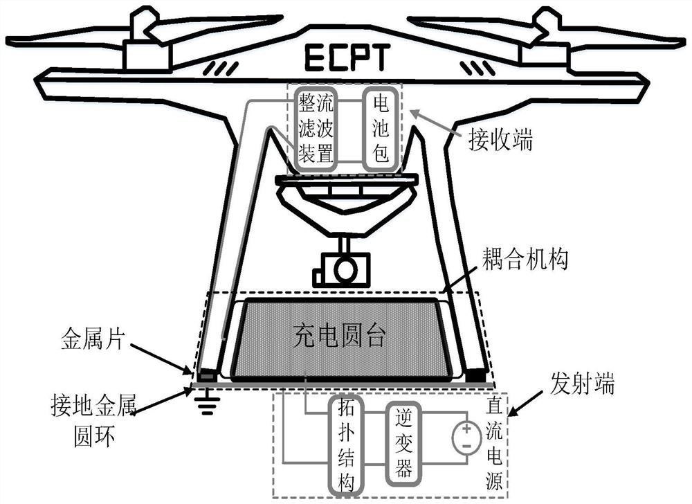
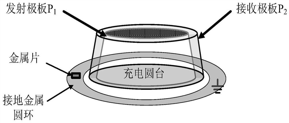
[0031] This embodiment mainly provides a single capacitive coupling mechanism for wireless charging of drones, such as figure 1 , figure 2 As shown, including the transmitting end and the receiving end, the transmitting end is provided with a charging round table with a small top and a large bottom. The body of the charging round table can be made of light insulating material, and its side is formed by laying a metal film to form the primary emitter plate P 1 ; The receiving end is provided with a circular truncated receiving cover that cooperates with the charging circular platform. The body of the circular truncated receiving cover is also made of light insulating material, and its side is formed by laying a metal film to form a secondary receiving plate P 2 The primary emitter plate and the secondary receive plate form a single-capacitance electric field coupling mechanism to implement wireless charging. During specific implementation, insulation can be provided on the out...
Embodiment 2
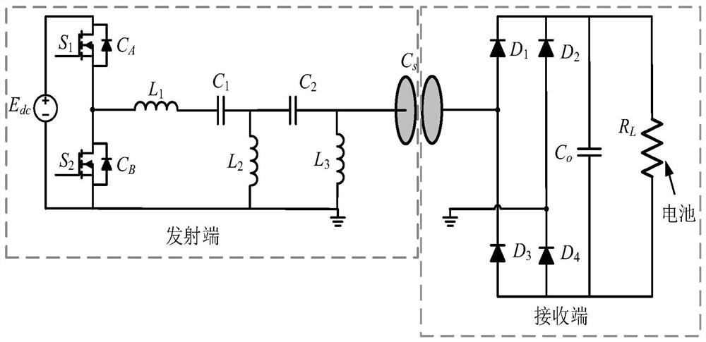
[0041] Such as image 3 As shown, this embodiment provides a wireless charging system for drones, based on the single capacitive coupling mechanism for wireless charging provided in Embodiment 1, the transmitting end is also provided with a DC power supply, an inverter and a primary circuit Topological structure, the receiving end is also provided with a rectifying and filtering device and a rechargeable battery pack, one of the input terminals of the rectifying and filtering device is directly connected to the receiving plate of the secondary side, and the other is directly connected to the metal sheet. In this example, the inverter adopts a half-bridge inverter, and the topology of the primary side circuit includes the resonant inductor L 1 , Resonant inductance L 2 , Resonant inductance L 3 , Resonant capacitance C 1 and resonant capacitor C 2 , the resonant capacitor C 1 , Resonant inductance L 2 and resonant capacitor C 2 Constitute a T-type CLC resonant network, r...
Embodiment 3
[0062]Provide a drone that can adopt figure 1 The installation structure shown uses the wireless charging system provided in Embodiment 2 to perform wireless charging.
[0063] Small unmanned aerial vehicles are often used in civilian applications and have a wide range of uses, such as line inspection, photography, monitoring data, etc. Generally speaking, in order to increase the battery life, small UAVs have a lighter load and a smaller battery capacity, and usually require a charging power of about 100 watts.
[0064] In order to verify the effect that the present invention mentions, also according to below image 3 The shown ECPT system topology establishes the simulation circuit model of the system on the LT-spice simulation platform. Set R according to the battery parameters of the small drone L The value of E is set according to the formula (6) and the output power requirement of the small UAV battery dc and the value of k, set C according to the UAV's appearance co...
PUM
 Abstract
Description
Claims
Application Information
 - R&D
- Intellectual Property
- Life Sciences
- Materials
- Tech Scout
- Unparalleled Data Quality
- Higher Quality Content
- 60% Fewer Hallucinations
Browse by: Latest US Patents, China's latest patents, Technical Efficacy Thesaurus, Application Domain, Technology Topic, Popular Technical Reports.
© 2025 PatSnap. All rights reserved.Legal|Privacy policy|Modern Slavery Act Transparency Statement|Sitemap|About US| Contact US: help@patsnap.com


