Unmanned aerial vehicle electric field coupling mechanism, wireless charging system, platform and unmanned aerial vehicle

A coupling mechanism and wireless charging technology, applied in the field of unmanned aerial vehicles, can solve the problems of conductor eddy current loss, large electromagnetic interference in the surrounding environment, high cost, and achieve the effect of low power consumption operation

Active Publication Date: 2020-11-24
CHONGQING UNIV
View PDF6 Cites 4 Cited by
  • Summary
  • Abstract
  • Description
  • Claims
  • Application Information

AI Technical Summary

Problems solved by technology

[0004] In terms of wireless charging for UAVs, most of the researches of domestic and foreign scholars focus on magnetic field coupling. Although wireless charging can be realized, it still has the following disadvantages: 1) The coupling coil and magnetic core of the system increase the weight of

Method used


Image

  • Unmanned aerial vehicle electric field coupling mechanism, wireless charging system, platform and unmanned aerial vehicle
  • Unmanned aerial vehicle electric field coupling mechanism, wireless charging system, platform and unmanned aerial vehicle
  • Unmanned aerial vehicle electric field coupling mechanism, wireless charging system, platform and unmanned aerial vehicle

Examples


Embodiment 1

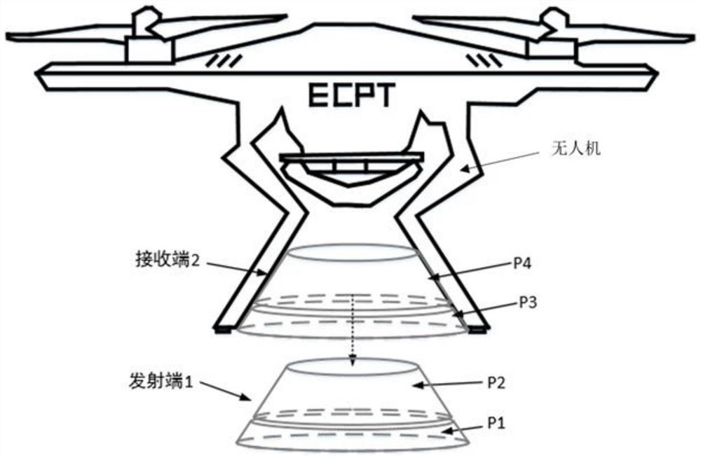
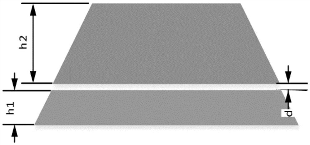
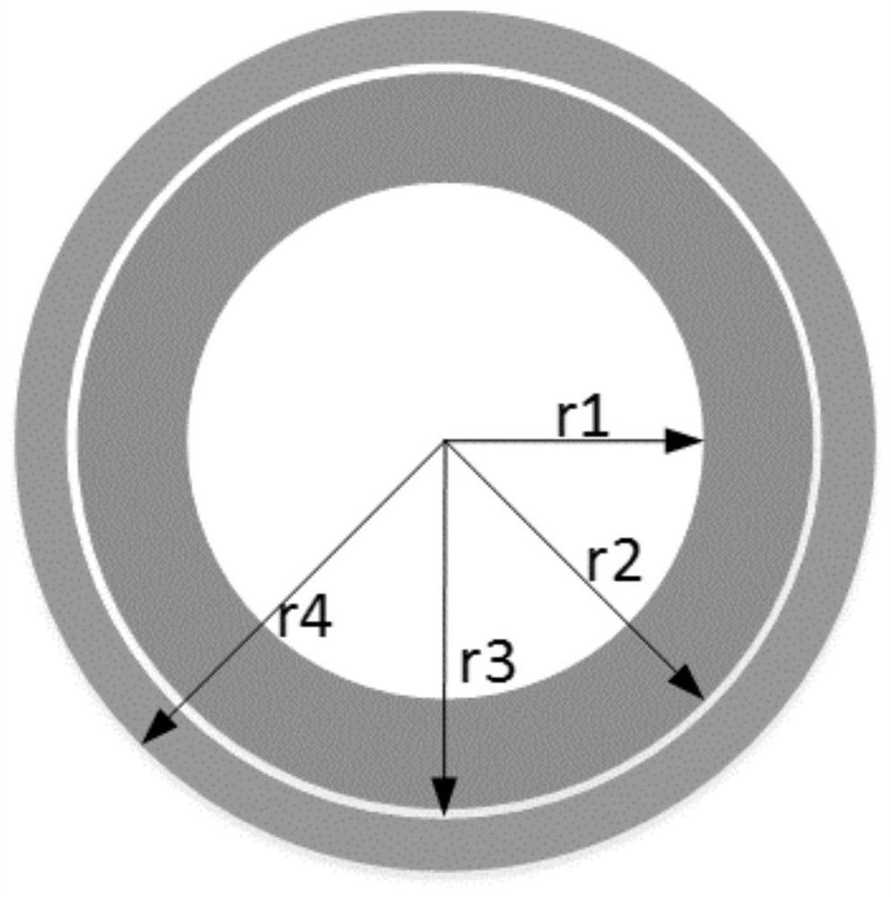
[0038] The embodiment of the present invention provides an unmanned aerial vehicle electric field coupling mechanism, a new type of "round table" coupling mechanism, its structure is as follows figure 1 As shown, it includes transmitter 1 and receiver 2. The front view / left view of the receiving end 2 is as follows figure 2 As shown, the top view is as image 3 shown.

[0039] The transmitting end 1 includes an upper circular platform P2 at the transmitting end and a lower circular platform P1 at the transmitting end at a distance from the first preset height, and the receiving end 2 includes a hollow upper circular platform P4 at the receiving end (the height is h2, and the inner diameter is r2~ r1) and the hollow lower circular platform P3 at the receiving end (its height is h1, and its inner diameter is r4~r3).

[0040] The transmitting end 1 is made of solid insulating material, the outer surface is covered with the first metal foil, and the receiving end 2 is made of ...

Embodiment 2

[0049] At present, UAV, as a mobile device with weak battery life, needs to be charged and discharged frequently. During the frequent moving in and out, it may cause damage to the ECPT circuit system. This embodiment aims to propose a new type of wireless charging system for drones based on electric field coupling while meeting the charging requirements of drones. The system selects a suitable coupling mechanism and resonant network to ensure that no excessive voltage and current impacts are generated during the moving in and out of the UAV, and when the UAV moves in, the system can efficiently and stably provide the required power for the load. Power; when the drone is removed, the system can automatically enter standby mode and maintain low power consumption.

[0050] This embodiment provides a UAV wireless charging system based on electric field coupling (Double T UAV ECPT system), including a transmitting circuit and a receiving circuit, and the transmitting circuit includ...

Embodiment 3

[0109] This embodiment provides a wireless charging platform for drones, including the transmitting circuit described in Embodiment 2. Similarly, the first electric energy emitting plate and the second electric energy emitting plate in the transmitting circuit of this embodiment are shown in the embodiment. The upper circular platform P2 at the transmitting end and the lower circular platform P1 at the transmitting end.

[0110] In other embodiments, other electric energy emitter plates can be used, such as a common flat plate structure, but the charging effect will also vary depending on the structure.

[0111] In other embodiments, the power supply E dc , The full-bridge inverter can be replaced by other circuits with the same function.


PUM

PropertyMeasurementUnit
Thicknessaaaaaaaaaa

Abstract

The invention relates to the technical field of unmanned aerial vehicle wireless charging, and in particular discloses an unmanned aerial vehicle electric field coupling mechanism, a wireless chargingsystem, a platform and an unmanned aerial vehicle. The unmanned aerial vehicle electric field coupling mechanism comprises a transmitting end and a receiving end, the transmitting end comprises a transmitting end upper circular truncated cone and a transmitting end lower circular truncated cone which are separated from each other by a first preset height, and the receiving end comprises a receiving end hollow upper circular truncated cone and a receiving end hollow lower circular truncated cone which are separated from each other by a second preset height; the transmitting end is made of solid insulating materials, the outer side face is covered with first metal foil, the receiving end is made of light insulating materials, and the inner side face is covered with second metal foil. Insulating isolation layers are arranged on the outer surface of the first metal foil or/and the outer surface of the second metal foil. The coupling mechanism can improve the anti-offset capability of thecharging system and reduce the flight power consumption of the unmanned aerial vehicle, the cost is low, too high voltage and current impact is not generated in the moving-in and moving-out processesof the unmanned aerial vehicle, and when metal conductors exist between the coupling mechanisms or around the coupling mechanisms, eddy current loss of the conductors cannot be caused.

Description

technical field [0001] The present invention relates to the technical field of wireless charging for drones, in particular to an electric field coupling mechanism for drones, a wireless charging system for drones based on electric field coupling, a wireless charging platform for drones and a drone. Background technique [0002] Unmanned aerial vehicle (Unmanned Aerial Vehicle, UAV) is an unmanned aircraft controlled by radio remote control equipment and its own program control device, or completely or intermittently operated autonomously by an on-board computer. In recent years, my country's civilian drone market has shown a blowout development, and drones have begun to be used in many fields. From the fields such as film and television aerial photography, agricultural plant protection, infrastructure inspection, security rescue, geographic surveying and mapping that have become popular now, to the future civilian drone technology will enter all walks of life like computers....

Claims


Application Information

Patent Timeline
IPC IPC(8): H02J7/02H02J50/12H02J50/70H02J50/40B60L53/12B64F1/00
CPCH02J7/02H02J50/12H02J50/70H02J50/40B60L53/12B64F1/00B60L2200/10Y02T10/70Y02T10/7072Y02T90/14
Inventor 苏玉刚詹文杰戴欣唐春森王智慧孙跃
Owner CHONGQING UNIV
Why Eureka
Try Eureka