Self-adaptive generator comprehensive protection device

A technology for comprehensive protection devices and generators, applied in electromechanical devices, machines/engines, cooling/ventilation devices, etc., can solve problems such as harsh outdoor conditions, generator damage, and affecting generator work

Pending Publication Date: 2020-09-08
南京苏继电力技术有限公司
View PDF4 Cites 3 Cited by
  • Summary
  • Abstract
  • Description
  • Claims
  • Application Information

AI Technical Summary

Problems solved by technology

[0005] The purpose of the present invention is to provide a comprehensive protection device for self-adaptive generators. It is easy to be damaged during use, thus affecting the technical problems of the normal operation of the generator

Method used


Image

  • Self-adaptive generator comprehensive protection device
  • Self-adaptive generator comprehensive protection device
  • Self-adaptive generator comprehensive protection device

Examples


no. 1 example

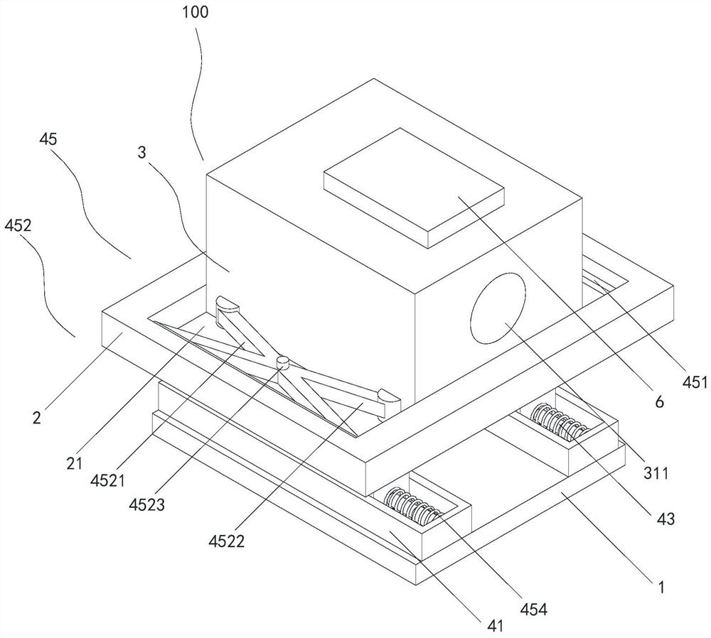
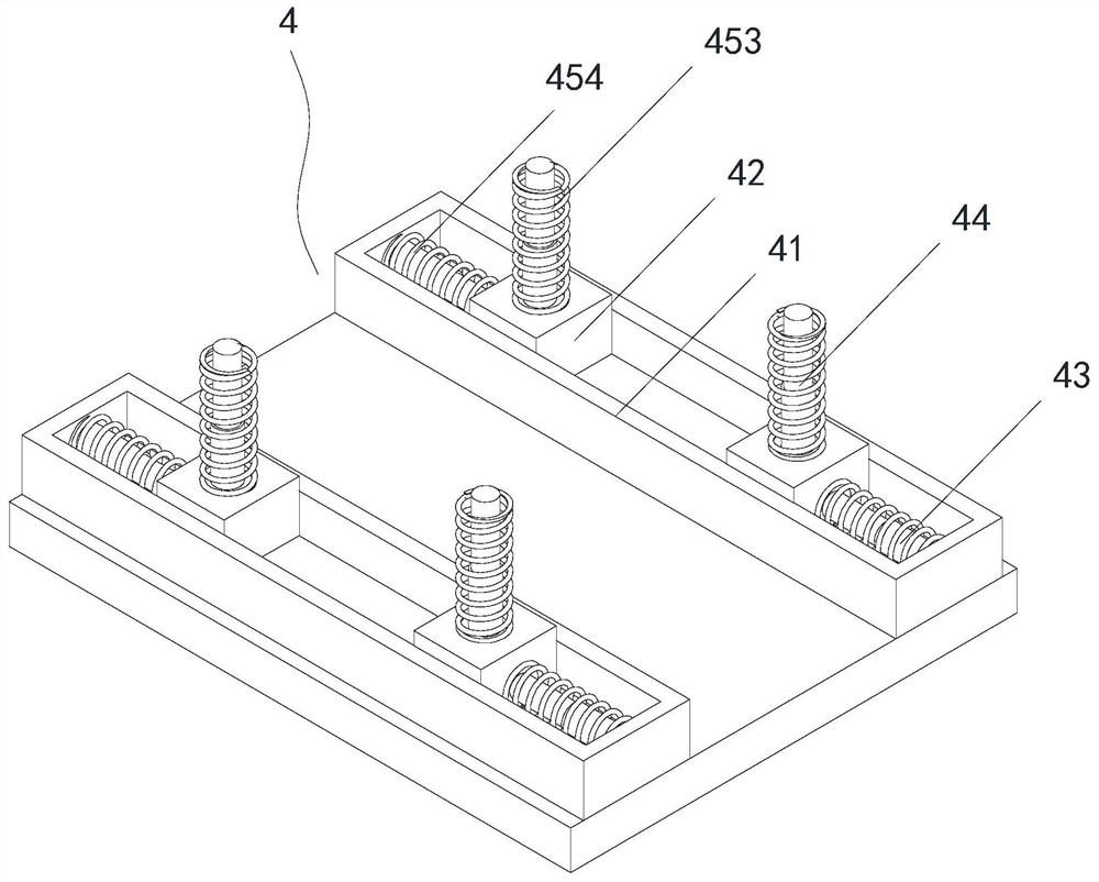
[0026] see Figure 1 to Figure 2 , the present invention provides an adaptive generator comprehensive protection device 100, including a base plate 1, a mounting base 2, a motor body 3 and a shock absorbing assembly 4; Connected and located above the bottom plate 1, the motor body 3 is slidingly connected with the mounting seat 2, and located on the side of the mounting seat 2 away from the bottom plate 1; the shock absorbing assembly 4 includes a first Slide rail 41, slider 42, horizontal hydraulic telescopic rod 43, vertical hydraulic support rod 44 and displacement restraining member 45, the first slide rail 41 is fixedly connected with the bottom plate 1, and is located near the bottom plate 1 One side of the mounting seat 2, the slider 42 is slidingly connected with the first slide rail 41, and is located on the side of the first slide rail 41 away from the bottom plate 1, and one end of the horizontal hydraulic telescopic rod 43 It is fixedly connected with the bottom p...

no. 2 example

[0032] see Figure 1 to Figure 3 , the present invention provides an adaptive generator comprehensive protection device 100, including a base plate 1, a mounting base 2, a motor body 3 and a shock absorbing assembly 4; Connected and located above the bottom plate 1, the motor body 3 is slidingly connected with the mounting seat 2, and located on the side of the mounting seat 2 away from the bottom plate 1; the shock absorbing assembly 4 includes a first Slide rail 41, slider 42, horizontal hydraulic telescopic rod 43, vertical hydraulic support rod 44 and displacement restraining member 45, the first slide rail 41 is fixedly connected with the bottom plate 1, and is located near the bottom plate 1 One side of the mounting seat 2, the slider 42 is slidingly connected with the first slide rail 41, and is located on the side of the first slide rail 41 away from the bottom plate 1, and one end of the horizontal hydraulic telescopic rod 43 It is fixedly connected with the bottom p...

no. 3 example

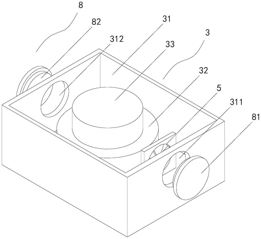
[0038] see Figure 1 to Figure 4, the present invention provides an adaptive generator comprehensive protection device 100, including a base plate 1, a mounting base 2, a motor body 3 and a shock absorbing assembly 4; Connected and located above the bottom plate 1, the motor body 3 is slidingly connected with the mounting seat 2, and located on the side of the mounting seat 2 away from the bottom plate 1; the shock absorbing assembly 4 includes a first Slide rail 41, slider 42, horizontal hydraulic telescopic rod 43, vertical hydraulic support rod 44 and displacement restraining member 45, the first slide rail 41 is fixedly connected with the bottom plate 1, and is located near the bottom plate 1 One side of the mounting seat 2, the slider 42 is slidingly connected with the first slide rail 41, and is located on the side of the first slide rail 41 away from the bottom plate 1, and one end of the horizontal hydraulic telescopic rod 43 It is fixedly connected with the bottom pl...


PUM


Abstract

The invention discloses a self-adaptive generator comprehensive protection device. Vibration is generated when the motor body generates power. A vertical hydraulic supporting rod and a vertical supporting spring are used for supporting a mounting base; the vibration amplitudes of the mounting base and the motor body are reduced; the motor body and the mounting base move back and forth together; asliding block is supported by the transverse hydraulic telescopic rod and the transverse supporting spring. The displacement distance of the motor body is reduced; when the motor body moves transversely in the placing groove of the mounting base, the motor body is supported by the first connecting support and the second connecting support, and movement of the motor body is slowed down through sliding of the bearing connecting rod, so that the motor body can be damped during vibration, internal elements of the motor body are prevented from being damaged during vibration, and the motor body canwork normally.

Description

technical field [0001] The invention relates to the technical field of generators, in particular to an adaptive generator comprehensive protection device. Background technique [0002] At present, electric energy is one of the most important energy sources in modern society. A generator is a mechanical device that converts other forms of energy into electric energy. It is driven by a water turbine, steam turbine, diesel engine or other power machinery to convert water flow, air flow, fuel combustion or nuclear fission. The generated energy is converted into mechanical energy and transmitted to the generator, and then converted into electrical energy by the generator, so that the generator has a wide range of uses in industrial and agricultural production, national defense, science and technology, and daily life. [0003] There are many types of generators, but their working principles are based on the law of electromagnetic induction and the law of electromagnetic force. The...

Claims


Application Information

Patent Timeline
IPC IPC(8): H02K5/24H02K9/04F04D27/00
CPCH02K5/24H02K9/04F04D27/008
Inventor 刘明强
Owner 南京苏继电力技术有限公司
Why Eureka
Try Eureka