Oil stain decomposition and adsorption device for oil-containing waste gas treatment

A waste gas treatment and adsorption device technology, which is applied in the direction of combination device, separation method, dispersed particle separation, etc., to achieve the effect of avoiding adsorption clogging

Inactive Publication Date: 2020-09-11
戚永团
View PDF12 Cites 4 Cited by
  • Summary
  • Abstract
  • Description
  • Claims
  • Application Information

AI Technical Summary

Problems solved by technology

[0007] Aiming at the problems existing in the prior art, the object of the present invention is to provide an oil stain decomposing and adsorbing device for treating oily waste gas, which pushes the oil stain dispersant in the annular feeding pan to several The strip-shaped arc-shaped embedded board penetrates outwards through multiple elastic telescopic feeding bags, and the oil stain dispersant that penetrates outwards is dispersed on the filler skeleton through the feeding diffusion mechanism, and is used to clean the oil stains attached to the filler skeleton. Decomposition and diffusion can effectively avoid blockage caused by excessive oil stains attached to the filler skeleton. In addition, an elastic bag layer filled with an inflatable gas layer is arranged at the inner end of the strip-shaped arc-shaped embedded plate. When the imported exhaust gas diffuses outward through the filler skeleton When the exhaust gas with a certain impact force can exert a certain squeezing effect on the elastic bag layer, it is easier for the oil dispersant to penetrate outward. When the exhaust gas is not introduced, the elastic telescopic feed bag resets and shrinks, thus effectively Prevent the oil dispersant from penetrating outward

Method used


Image

  • Oil stain decomposition and adsorption device for oil-containing waste gas treatment
  • Oil stain decomposition and adsorption device for oil-containing waste gas treatment
  • Oil stain decomposition and adsorption device for oil-containing waste gas treatment

Examples


Embodiment 1

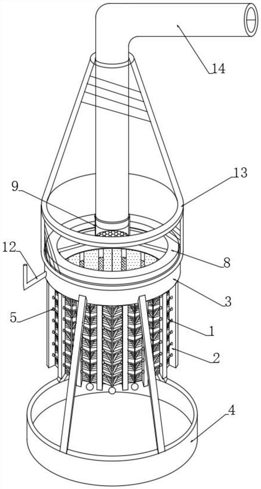
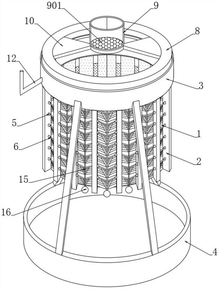
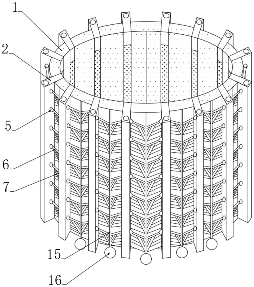
[0038] see Figure 1-2 , an oil stain decomposition and adsorption device for oily waste gas treatment, comprising a filler skeleton 1 and a plurality of strip-shaped arc-shaped embedded plates 2 embedded and connected to the side walls around the filler skeleton 1, the strip-shaped arc-shaped embedded plates 2 are Porous ceramic filler skeleton, the porous ceramic filler skeleton is filled with biochar, the thickness of the porous ceramic filler skeleton is 1.5-3cm, the top of the filler skeleton 1 is fixedly connected with a plurality of strip-shaped arc-shaped embedded plates 2 internally communicated Ring-shaped feed pan 3, the four corners of the lower end of the ring-shaped feed pan 3 are fixedly connected with a disc base 4 through a support frame, and the top end of the annular feed pan 3 is slidably and sealedly connected with an annular squeeze disc 8, and the ring-shaped squeeze disc 8 The top end is connected with a push-down mechanism, and the ring-shaped feeding ...


PUM

PropertyMeasurementUnit
thicknessaaaaaaaaaa

Abstract

The invention discloses an oil stain decomposition and adsorption device for oil-containing waste gas treatment, and belongs to the technical field of waste gas treatment. The pushing force during waste air intake is utilized; an oil stain dispersing agent in an annular feeding disc is pushed into a plurality of strip-shaped arc-shaped embedding plates to permeate outwards by a plurality of elastic telescopic feeding bags; the oil stain dispersing agent which permeates outwards is dispersed on a filler framework through a feeding diffusion mechanism, and is used for decomposing and diffusing oil stains attached to the filler framework. Blockage caused by excessive oil stains attached to the filler framework is effectively avoided; besides, an elastic bag layer filled with an expansion gaslayer is arranged at the inner end of the strip-shaped arc-shaped embedding plate, when guided-in waste gas diffuses outwards through the filler framework, the waste gas with certain impact force canplay a certain role in extruding the elastic bag layer, so that the oil stain dispersing agent permeates outwards more easily, and under the condition that the waste gas is not guided in, the elastictelescopic feeding bags reset and contract, so that the oil stain dispersing agent is effectively prevented from permeating outwards.

Description

technical field [0001] The invention relates to the technical field of waste gas treatment, in particular to an oil stain decomposition and adsorption device for oily waste gas treatment. Background technique [0002] Existing printing and dyeing, petrochemical, paint and other fields will emit high-concentration and high-temperature organic waste gases such as gasoline, naphtha, and benzene during the processing process, such as gasoline, naphtha, and benzene. If they are directly discharged, not only It will pollute the environment and cause the greenhouse effect of the atmosphere. In addition, the exhaust gas contains some combustible oil stains, which will cause major fire or explosion hazards in harsh environments. [0003] Organic waste gas treatment is the treatment of adsorption, filtration and purification of organic waste gas generated in the process of industrial production. Common treatment methods: adsorption method, absorption method, biological reagent spray ...

Claims


Application Information

Patent Timeline
Patent Type & Authority Applications(China)
IPC IPC(8): B01D49/00B01D50/00
CPCB01D49/00B01D50/00
Inventor 戚永团
Owner 戚永团
Why Eureka
Try Eureka