A graded slurry stirring device
A technology of stirring device and installation location
- Summary
- Abstract
- Description
- Claims
- Application Information
AI Technical Summary
Problems solved by technology
Method used
Image
Examples
Embodiment 1
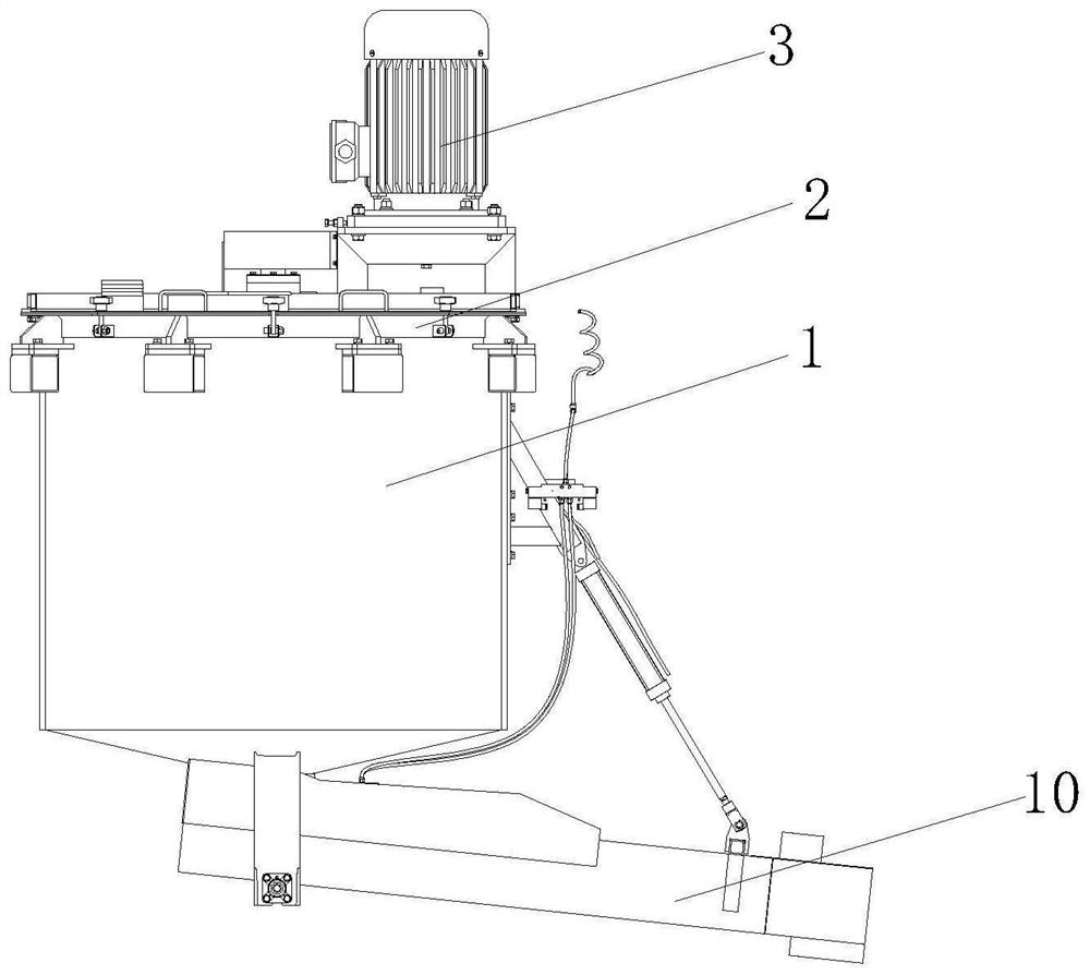
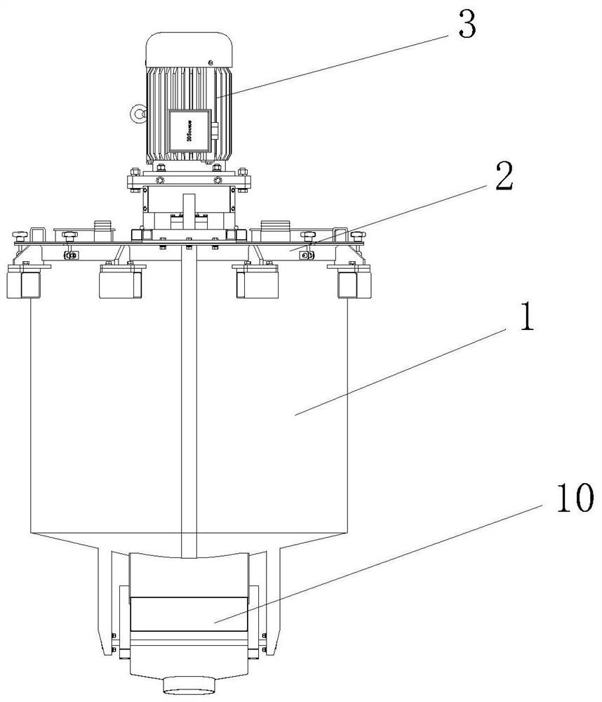
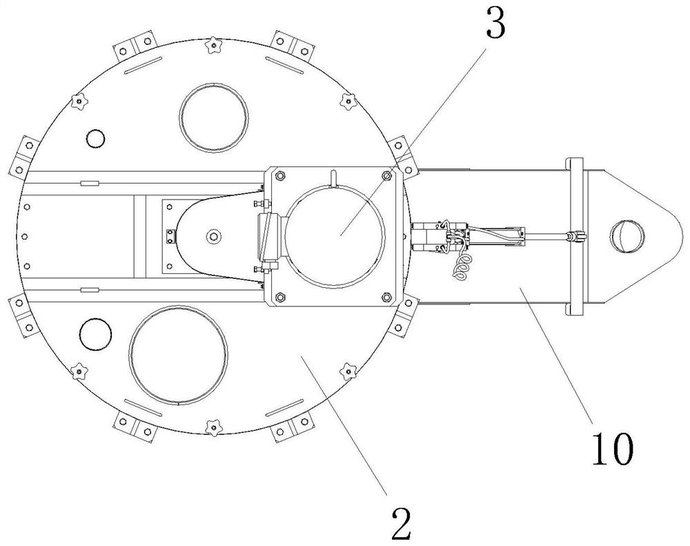
[0030] Embodiment 1, according to Figure 4-7 When stirring the slurry, after opening the cover plate 2, the valve 11 on the side wall of the salted fish injection device 6 of the external input device is connected to the valve 11. After the injection device 6 is filled, the external input device is withdrawn, and then Inject the first-grade slurry into the inside of the tank body 1, cover the cover plate 2, connect the output end of the motor 3 with the speed-up gear 7, and drive the speed-up gear 7 to rotate through the drive of the output end of the motor 3. The differential rotation between the speed gears 7 makes the slurry injected in the injection device 6 be injected in stages, and the stirring blades 8 rotate synchronously, so that before the slurry in the injection device 6 of the next stage is injected, the slurry in the upper stage The slurry injected by the injection device 6 has been mixed inside the tank body 1, thereby improving the mixing effect, improving the...
Embodiment 2
[0031] Example 2, such as Figure 4-5 and Figure 7, when the speed-up gear 7 is connected to the output end of the motor 3, the speed-up gear 7 is driven to rotate by the output end of the motor 3. Since the number of teeth set on the speed-up gear 7 is different, the upper-level speed-up gear 7 is set When the teeth are in contact with the teeth in the upper groove of the next-stage speed-up gear 7, there will be a time difference, which will result in different speeds between the speed-up gears 7, so there is also a difference in the speed of the transmission ring gear 9, and The pressing plate 603 is affected by the meshing effect of the transmission gear group 9 and the driving gear 604, so that the injection speed of the injection device 6 will be different.
Embodiment 3
[0032] Example 3, such as Figure 6 , as the pressure inside the valve body 1101 continues to increase, the cut-off plate 1103 is under pressure and compresses the spring 1102, so that the material delivery pipeline 1104 provided inside the valve body 1101 is connected with the external device, so as to realize the injection of the material inside the injection device 6 and to the Slurry is injected into the inside of the tank body 1, and the cut-off plate 1103 can be reset by the elastic force of the spring 1102 itself.
[0033] Working principle: After opening the top cover plate 2 of the tank body 1, the external input pipe is connected to the valve 11 set on the injection device 6 through the external input device, and the slurry is injected into the injection material. When injecting, the cut-off plate 1103 receives the injection pressure and compresses the spring 1102, and opens the material delivery pipe 1104 to realize material injection. After the material injection i...
PUM
 Abstract
Description
Claims
Application Information
 - R&D
- Intellectual Property
- Life Sciences
- Materials
- Tech Scout
- Unparalleled Data Quality
- Higher Quality Content
- 60% Fewer Hallucinations
Browse by: Latest US Patents, China's latest patents, Technical Efficacy Thesaurus, Application Domain, Technology Topic, Popular Technical Reports.
© 2025 PatSnap. All rights reserved.Legal|Privacy policy|Modern Slavery Act Transparency Statement|Sitemap|About US| Contact US: help@patsnap.com


