
A heavy hammer assembly of a bucket wheel stacker and reclaimer

A bucket wheel stacker-reclaimer and heavy hammer technology, which is applied in the directions of transportation, packaging, loading/unloading, etc., can solve the problem of unclear connection stability and force of the heavy hammer, unclear specific structure of the heavy hammer, and influence on the force. and balance adjustment, to achieve the effect of good bearing capacity and stability, maintaining force balance, and maintaining dispersed force

Active Publication Date: 2022-02-15
武汉三作全盛工程设计有限公司
View PDF10 Cites 0 Cited by
  • Summary
  • Abstract
  • Description
  • Claims
  • Application Information

AI Technical Summary

Problems solved by technology

[0003] For example, the Chinese utility model patent (CN203006517U) disclosed a coal storage yard conveyor in 2013, which has a bucket wheel stacker and reclaimer. , the column of the bucket-wheel stacker-reclaimer is equipped with a control room; the bucket-wheel stacker-reclaimer adjusts the counterweight of the entire mechanism by swinging the weight to maintain the balance of the mechanism, but the specific structure of the weight is not clear, and the weight of the weight The connection stability and stress situation are not clear
[0004] Moreover, most of the existing heavy hammers are assembled or welded on the end of the cantilever during installation, especially if the structure of the welded structure is unreasonable, defects such as cracks and deformation are likely to occur, which will affect the force and balance adjustment. After working outdoors for a long time, the heavy hammer is prone to safety problems due to the erosion of dust and rain

Method used


Image

  • A heavy hammer assembly of a bucket wheel stacker and reclaimer
  • A heavy hammer assembly of a bucket wheel stacker and reclaimer
  • A heavy hammer assembly of a bucket wheel stacker and reclaimer

Examples


Embodiment 1

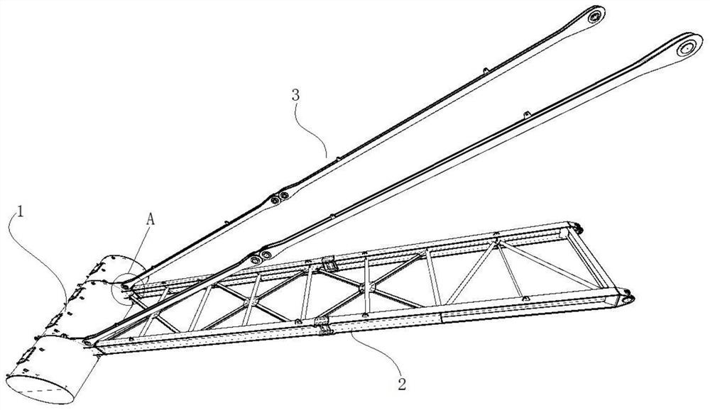
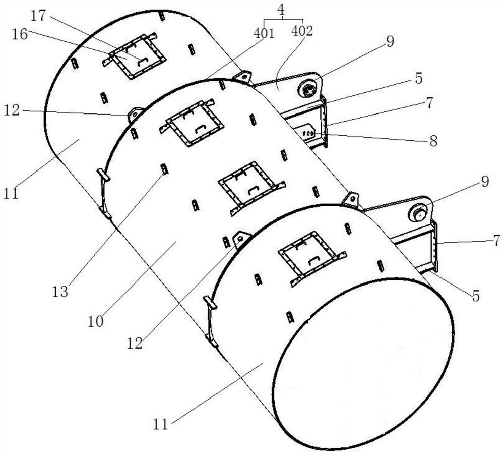
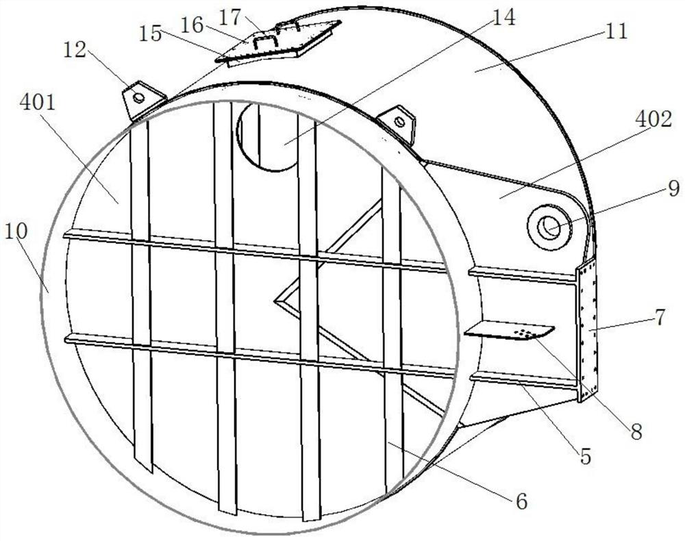
[0040] Such as Figure 1 to Figure 6 As shown, a heavy hammer assembly of a bucket wheel stacker reclaimer, the heavy hammer assembly includes a heavy hammer body 1, and a horizontal cantilever assembly 2 and a diagonal rod assembly 3 connected to the heavy hammer body 1; Hammer body 1 comprises a pair of cantilever plates 4 arranged in parallel, and said cantilever plates 4 have a circular portion 401 and a polygonal portion 402 (special-shaped plates, one side is arc-shaped, and the other sides are polygonal); each said cantilever plate 4 Both sides of the circular part 401 are respectively symmetrically provided with two transverse tie bars 5, and at least one side of the circular part 401 is provided with four vertical tie bars 6, and the end of the polygonal part 402 is provided with the cantilever Plate 4 is vertical to the main mounting plate 7, and the oblique upper corner of the polygonal part 402 is provided with a flange hole 9; a pair of cantilever plates 4 are wel...

Embodiment 2

[0057] This embodiment provides a structure of a horizontal cantilever assembly and a diagonal stay rod assembly.

[0058] Specifically as Figure 7 As shown, the horizontal cantilever assembly 2 includes a pair of main beams 201 arranged in parallel, and a number of parallel cross beams 202 are arranged at equal intervals between the pair of main beams 201, and the two ends of the cross beams 202 are respectively connected to the The inner side of the main beam 201 is fixed by cross welding; the middle part of the cross beam 202 is horizontally provided with a middle connecting plate 203, and the four corners of the middle connecting plate 203 are respectively screwed with section steel 204, and the other ends of the section steel 204 are respectively screw connected to On the main beam 201 on the corresponding side, every four of the section steels 204 and one of the middle connecting plates 203 form an "X"-shaped fixed structure; Figure 6 As shown, the end of the main bea...

Embodiment 3

[0064] This embodiment provides a structure in which the weight hammer assembly of the first embodiment is installed on the bucket wheel stacker and reclaimer.

[0065] Such as Figure 8 As shown, the ends of the horizontal cantilever assembly 2 and the inclined rod assembly 3 away from the weight body 1 are respectively hinged and fixed on the main tower 18, and the other side of the main tower 18 is respectively connected with a bucket wheel connection cantilever 19 and The bucket wheel is connected to the cantilever inclined rod 20; the vertical height of the horizontal cantilever assembly 2 is set higher than the height of the bucket wheel connected to the cantilever 19, and the vertical height of the weight body 1 is higher than the height of the wheel bucket 21.

[0066] The arrangement of this structure facilitates the adjustment of the pitch angle of the wheel bucket, and the weight body 1 can maintain the force balance of the main tower 18 under different angles and r...


PUM


Abstract

The invention discloses a heavy hammer assembly of a bucket wheel stacker and reclaimer, which includes a heavy hammer body, a horizontal cantilever assembly and a diagonal rod assembly; the heavy hammer body includes a pair of parallel cantilever plates, and the cantilever plates have a circular part and a polygonal part; the cantilever plate is provided with horizontal and vertical tension bars, and the end of the polygonal part is provided with a main mounting plate and a secondary mounting plate perpendicular to the cantilever plate, and the polygonal part A flange hole is provided at the oblique upper corner; a middle cylinder is welded between the cantilever plates, and an outer cylinder is arranged on the outside; the auxiliary mounting plate is welded horizontally at the intersection of the middle cylinder and the polygonal part The auxiliary mounting plate and the main mounting plate are provided with screw holes and are screwed and fixed with the horizontal cantilever assembly, and the flange hole is hinged and fixed with the diagonal rod assembly; the weight of the bucket wheel stacker reclaimer The component structure is simple and compact, the connection is firm, and the stability is good; it can play the purpose of adjusting the counterweight and balancing the bucket wheel reclaimer.

Description

technical field [0001] The invention relates to the technical field of bucket-wheel stackers and reclaimers, in particular to a weight assembly of a bucket-wheel stacker-reclaimer. Background technique [0002] With the advancement of national modernization and industrialization, the scale of manufacturing industry is getting larger and larger, and the demand for raw materials is also increasing. In bulk material transportation, bucket wheel stackers and reclaimers with large reclaiming capacity are needed. heap. Bucket wheel stacker and reclaimer refers to a high-efficiency loading and unloading machine used in large-scale dry bulk storage yards for continuous transportation that can both stack and reclaim materials. It is composed of a tape conveying arm that can tilt and swing horizontally and its front end bucket wheel, frame, and running mechanism. The tape can run in both directions. When picking up materials, the material is taken by the bucket wheel and sent out thr...

Claims


Application Information

Patent Timeline
Patent Type & Authority Patents(China)
IPC IPC(8): B65G65/04
CPCB65G65/04
Inventor 周鼎鑫梁源许洋郑诗雅肖婷黄松吕凯何萌刘一波张晋华张红卫
Owner 武汉三作全盛工程设计有限公司
Learn More