Lower die underframe assembly and hot-pressing lower die structure

A component and mold bottom technology, which is applied in textiles and papermaking, etc., can solve the problems of inconvenient maintenance and repair, troublesome processing and manufacturing, and difficult to guarantee high-precision coordination.

Pending Publication Date: 2020-09-11
徐允聪
View PDF0 Cites 0 Cited by
  • Summary
  • Abstract
  • Description
  • Claims
  • Application Information

AI Technical Summary

Problems solved by technology

This kind of dynamic upper mold structure, which adopts the hot pressing upper mold and the lower pressure clamping mold driven by the gas-hydraulic booster cylinder, has the disadvantages of troublesome processing and manufacturing, difficulty in ensuring high-precision matching, and inconvenient maintenance and repair.
When the gas-liquid pressurized cylinder drives the mold to move up and down, it is essentially a cylinder. Due to the compressibility of compressed air, the movement rigidity of the cylinder is poor. When the hot-pressed upper mold moves up and down, it will appear due to the change of resistance. Instability and shocks such as crawling or jumping
Since the moving mold is placed on the top, after the gas-hydraulic pressurized cylinder is used for a long time, oil leakage will inevitably occur due to the wear of the seal, which may cause direct contamination of the hot-pressing mold and the product.
In addition, in the case of unexpected power failure and long-term shutdown, there is a potential safety hazard that the upper meme will fall due to its own weight and damage the mold. Additional costs must be added to install safety auxiliary facilities

Method used


Image

  • Lower die underframe assembly and hot-pressing lower die structure
  • Lower die underframe assembly and hot-pressing lower die structure
  • Lower die underframe assembly and hot-pressing lower die structure

Examples


Embodiment 1

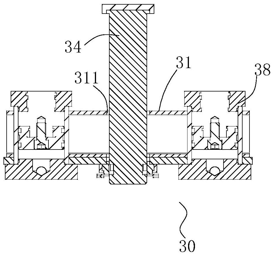
[0054] Please refer to Figure 1-4 , this embodiment provides a lower mold chassis assembly 30, including:

[0055] The chassis main body 31, the bottom chassis main body 31 is formed with a connecting shaft penetration hole 311 passing through its top surface and bottom surface;

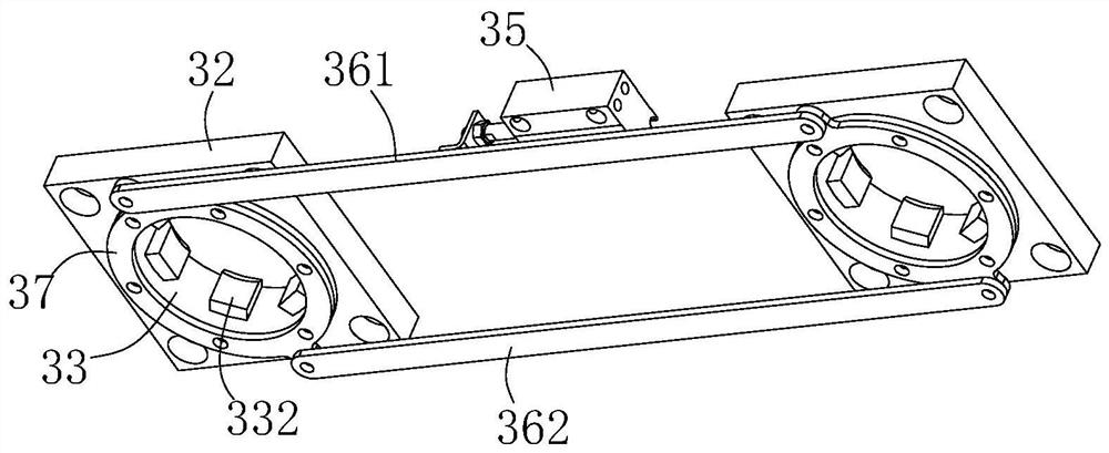
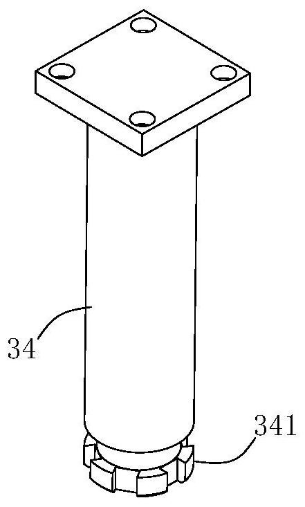
[0056] Locking mechanism, the locking mechanism comprises axle sleeve installation plate 32, rotating axle sleeve 33 and connecting shaft 34; The insertion hole 321 connected with the insertion hole 311; the rotating sleeve 33 is rotatably mounted on the sleeve installation plate 32, and the rotating sleeve 33 has a central through hole communicated with the insertion hole 321 arranged along its axial direction 331, a plurality of first splines 332 are arranged at intervals in the circumferential direction of the central through hole 331 of the rotating shaft sleeve 33; the connecting shaft 34 is arranged directly above the chassis main body 31, and its lower end is facing the connecting shaft inse...

Embodiment 2

[0061] refer to Figure 1-15 , this embodiment provides a hot pressing lower die structure, including: a hot pressing lower die assembly 10, a lower die mounting substrate 20, a lower die chassis assembly 30 of Embodiment 1, a guide post 40 and a lifting cylinder 50;

[0062] The lower die mounting base plate 20 is located below the hot pressing lower die assembly 10, and the lower die mounting base plate 20 is provided with a piston rod penetration hole 21;

[0063] The lower mold chassis assembly 30 is located below the lower mold mounting substrate 20; the upper end of the connecting shaft 34 is fixedly connected to the bottom surface of the lower mold mounting substrate 20;

[0064] The upper end of the guide post 40 is fixedly connected to the hot pressing lower die assembly 10 through the lower die mounting substrate 20 , and the lower end thereof is fixedly connected to the lower die chassis assembly 30 ;

[0065] The cylinder body of the lifting cylinder 50 is fixedly...


PUM


Abstract

The invention discloses a lower die underframe assembly and a hot-pressing lower die structure. The lower die underframe assembly comprises an underframe main body and a lock catch mechanism, and an insertion hole is formed in the underframe main body; the lock catch mechanism comprises a shaft sleeve mounting plate, a rotating shaft sleeve and a connecting shaft; a plurality of first splines arearranged at intervals in the circumferential direction of the central through hole of the rotating shaft sleeve; a plurality of second splines are arranged at intervals in the circumferential direction of the outer wall of the lower end part of the connecting shaft; a first driving mechanism is mounted on the bottom surface of the underframe main body; the first driving mechanism is used for driving the rotating shaft sleeve to be switched between an unlocking state and a locking state. The lower die underframe assembly has a locking function, can ensure that the underframe main body is lockedand restrained by the lock catch mechanism to keep still when the die is closed, and also has a pressurization function. The hot-pressing lower die structure has the locking and pressurizing functions, the operation stability is good, the hot-pressing pressure is adjustable, possible leakage points are located below a die and a product, and the die and the product are prevented from being polluted.

Description

technical field [0001] The invention relates to the technical field of hot pressing and shaping, in particular to a lower mold chassis assembly and a hot pressing lower mold structure. Background technique [0002] At present, pulp molding is a green and environmentally friendly product made of plant fiber pulp or waste paper products that can be completely naturally degraded and recycled. The production process of pulp molding consists of pulping, adsorption molding, wet embryo transfer, The process of hot pressing and shaping is completed; it is widely used in the fields of food and drug storage, electrical packaging, planting and seedling cultivation, medical utensils, handicraft base blanks, and fragile liner packaging. [0003] In the prior art, the hot-press shaping mold used in the hot-press shaping process includes a hot-press upper die and a hot-press lower die corresponding to the upper and lower sides. Most production equipment uses gas-hydraulic pressurized cyli...

Claims


Application Information

Patent Timeline
Patent Type & Authority Applications(China)
IPC IPC(8): D21J5/00
CPCD21J5/00
Inventor 徐罗申徐允聪
Owner 徐允聪
Why Eureka
Try Eureka