Centrifugal water pump

A technology of centrifugal water pump and pump body, applied in the field of centrifugal pump, can solve the problems of affecting pump efficiency, high cost, energy waste, etc., and achieve the effect of simple structure and low cost

Active Publication Date: 2020-09-11
安徽凯润泵阀科技有限公司
View PDF7 Cites 4 Cited by
  • Summary
  • Abstract
  • Description
  • Claims
  • Application Information

AI Technical Summary

Problems solved by technology

The existing centrifugal pump can only change the displacement of the pump by adjusting the speed, which will not only affect the efficiency of the pump, the head of the pump, but also need a speed regulating mechanism to control
Due to the high cost of speed regulating mechanisms such as frequency converters, when different flow rates are required, it is now widely used to control them by changing the pipeline characteristics through throttle valves, resulting in a lot of energy waste

Method used


Image

  • Centrifugal water pump
  • Centrifugal water pump
  • Centrifugal water pump

Examples


Embodiment Construction

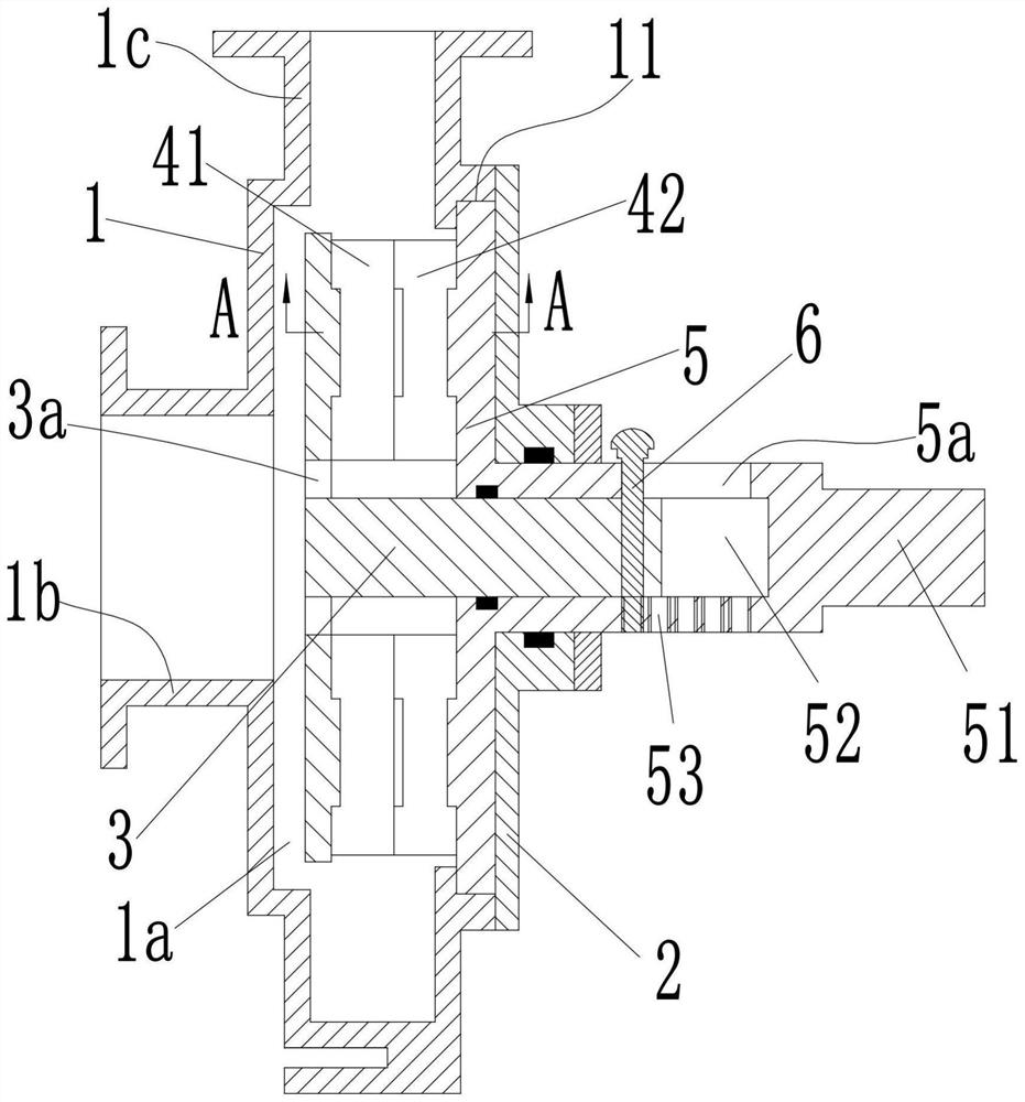
[0016] see Figure 1-4 As shown, a centrifugal water pump includes a pump body 1, a pump chamber 1a is arranged in the pump body 1, a pump cover 2 is fixedly installed at the opening of the right end of the pump chamber 1a, and a pump cover 2 is rotatably connected with A power shaft 51, said power shaft 51 is provided with a first disc 5 along the radial direction at one end located in the pump cavity 1a; said pump body 1 is provided with a turning groove 11 on the inner circumferential side wall of the opening at the right end, said first The outer circumference of the wheel disc 5 is rotatably connected in the rotating groove 11; the side of the pump body 1 is provided with a water inlet pipe 1b along the axial direction of the power shaft 51, and a water outlet pipe is provided along the radial direction of the first wheel disc 5 1c.

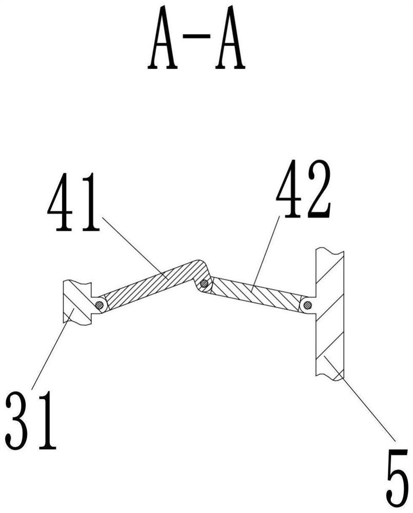
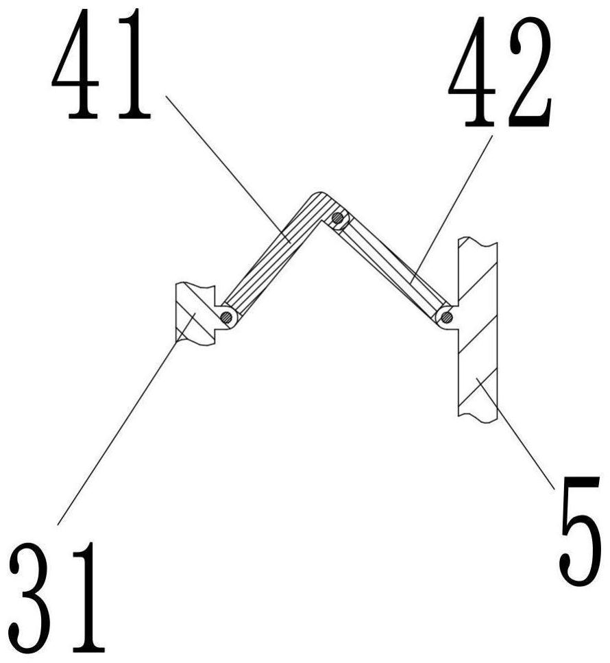
[0017] The power shaft 51 is provided with a chute 52 with an open left end. A protruding shaft 3 is slidably connected in the chute 52 al...


PUM


Abstract

The invention discloses a centrifugal water pump. The centrifugal water pump comprises a pump body, a pump cavity is formed in the pump body, a pump cover is fixedly installed at an opening in the right end of the pump cavity, a power shaft is rotationally connected into the pump cover, and a first wheel disc is arranged at one end of the power shaft; a water inlet pipeline and a water outlet pipeline are arranged on the side surface of the pump body; a sliding groove is formed in the power shaft, a protruding shaft is connected into the sliding groove in a sliding mode, and a second wheel disc is arranged at the left end of the protruding shaft; a plurality of first blades are hinged to the first wheel disc; a plurality of second blades are hinged to the second wheel disc; the first blades and the second blades are hinged to each other; when the protruding shaft slides leftwards, the first blades and the second blades are unfolded, the displacement of the centrifugal water pump is increased, and when the protruding shaft slides rightwards, the first blades and the second blades are folded, and the displacement of the centrifugal water pump is reduced; and the power shaft is provided with a push rod assembly for controlling the protruding shaft to slide left and right. The centrifugal water pump is simple in structure, and the displacement can be adjusted.

Description

technical field [0001] The invention belongs to the technical field of centrifugal pumps, in particular to a variable displacement centrifugal water pump. Background technique [0002] A centrifugal pump is a machine that transports or pressurizes a liquid. It transmits the mechanical energy of the prime mover or other external energy to the liquid to increase the energy of the liquid. It is mainly used to transport liquids including water, oil, acid and alkali, emulsion, suspension, etc. Emulsions and liquid metals, etc., can also transport liquids, gas mixtures, and liquids containing suspended solids; the technical parameters to measure the performance of centrifugal pumps include flow rate, suction lift, head, shaft power, water power, efficiency, etc. Existing centrifugal pumps can only change the displacement of the pump by adjusting the rotational speed, which not only affects the efficiency and head of the pump, but also requires a speed regulating mechanism to contr...

Claims


Application Information

Patent Timeline
Patent Type & Authority Applications(China)
IPC IPC(8): F04D1/00F04D15/00F04D29/22
CPCF04D1/00F04D15/0038F04D29/2222
Inventor 宋来瑞盛庆梅
Owner 安徽凯润泵阀科技有限公司
Why Eureka
Try Eureka