
High-speed centrifugal pump reverse rotation hydraulic turbine device

A hydraulic turbine, high-speed centrifugal technology, applied to the components of pumping devices for elastic fluids, reaction engines, pumps, etc., can solve the operating conditions without targeted consideration of small flow and high energy. The hydraulic loss in the inlet section of the hydraulic turbine and the difficulty of design and development of the hydraulic turbine are not considered, so as to achieve the effect of improving the efficiency of energy recovery and utilization, improving the efficiency of energy recovery and improving the efficiency of energy conversion

Pending Publication Date: 2020-09-11
ZHEJIANG SCI-TECH UNIV
View PDF2 Cites 0 Cited by
  • Summary
  • Abstract
  • Description
  • Claims
  • Application Information

AI Technical Summary

Problems solved by technology

However, for the working condition with relatively small flow rate but relatively high energy surplus, it is generally considered that the recoverable energy is low, and the design and development of the supporting hydraulic turbine is relatively difficult. The conventional method is to return the working fluid or use a pressure relief valve to vent, etc. Way to consume Fuyu energy, but this will cause great waste
[0003] In the field of petrochemical industry, the hydraulic turbine devices commonly used at home and abroad mainly use reverse pumps as hydraulic turbines. This type of hydraulic turbine is usually used for flow rates greater than 30m 3 / h working conditions, and there are generally problems such as relatively narrow high-efficiency zone and poor adaptability to flow conditions.
CN201020135834.0 discloses a design of the impeller inlet when the pump reverses as a hydraulic turbine. By changing the sharp angle of the impeller inlet, the efficiency of the pump reversed as a hydraulic turbine is improved, and the impact loss of the impeller inlet is reduced. However, this structure Does not take into account the operating conditions of small flow and high energy abundance
CN201710398967.3 discloses a hydraulic turbine in which the direction of the outlet of the casing and the direction of the impeller are perpendicular to each other, which solves the problem of serious loss of hydraulic efficiency when the fluid flows through the part between the outlet of the impeller and the outlet of the casing, but this structure does not Consideration of Hydraulic Loss in the Inlet Section of Hydraulic Turbine

Method used


Image

  • High-speed centrifugal pump reverse rotation hydraulic turbine device
  • High-speed centrifugal pump reverse rotation hydraulic turbine device
  • High-speed centrifugal pump reverse rotation hydraulic turbine device

Examples


Embodiment Construction

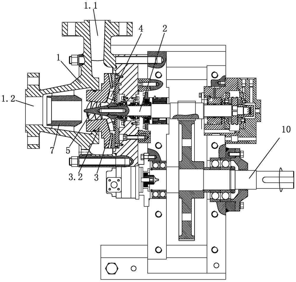
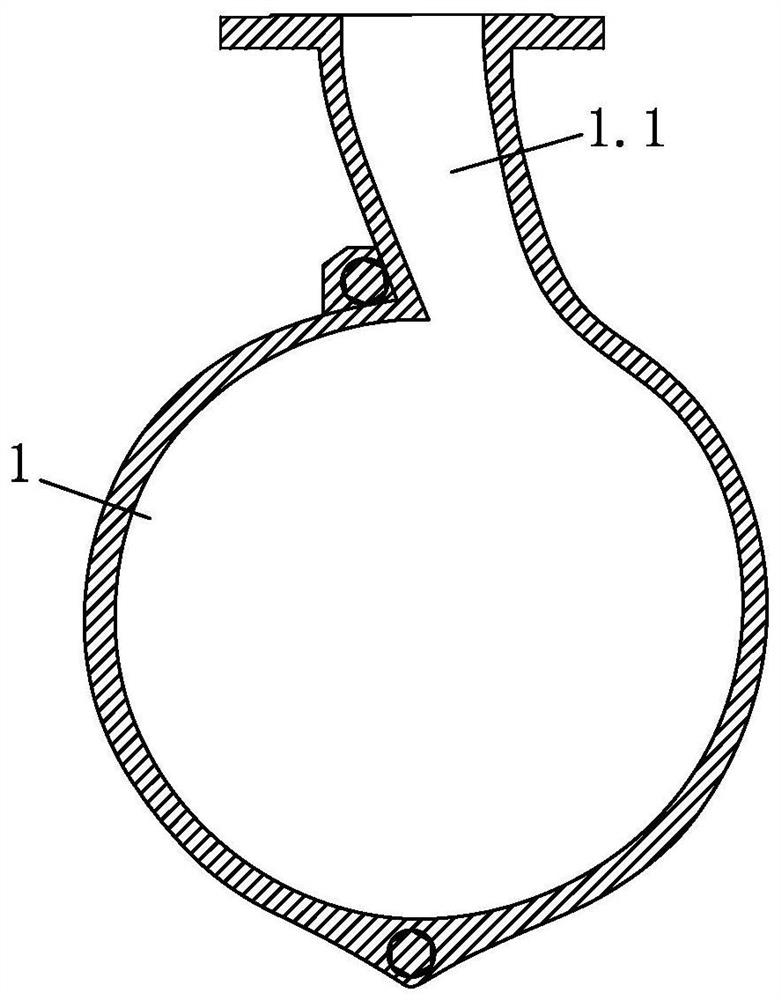
[0023] The traditional centrifugal pump works in reverse as a hydraulic turbine, including a turbine shaft, a volute, and an impeller. The impeller is set in the inner cavity of the volute. The turbine shaft and the impeller are fixed so that they can rotate together with the impeller. The turbine shaft passes through the gear box. The main shaft 10 is then connected to a generator set or load through a coupling. The traditional hydraulic turbine principle is: high-pressure fluid flows into the volute from the inlet section, and its pressure energy is converted into kinetic energy to drive the impeller and turbine shaft to rotate, and finally flows out from the outlet section. The turbine shaft drives the generator set or load to perform external work. , Complete the energy recovery and utilization of high-pressure mobile working fluid.

[0024] The present invention will be further described below in conjunction with the accompanying drawings of the specification, but the presen...


PUM


Abstract

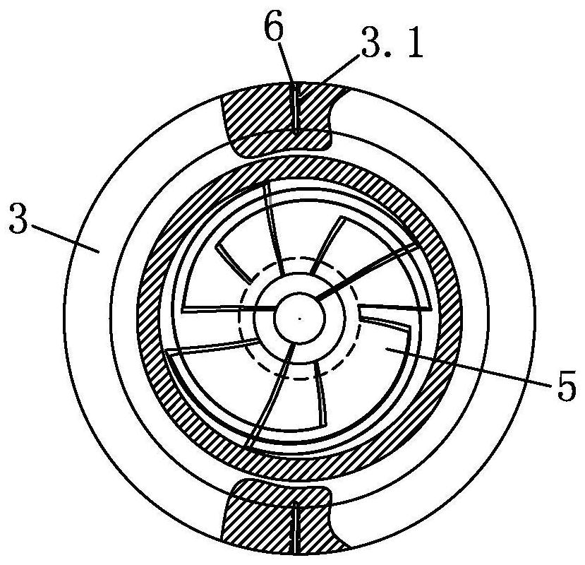
The invention belongs to the field of fluid machinery and energy recovery. According to the technical scheme, a high-speed centrifugal pump reverse rotation hydraulic turbine device is characterized by comprising a volute, a turbine shaft, a flow guide shell fixed in an inner cavity of the volute, an impeller rotationally positioned in the flow guide shell and connected with the left end of the turbine shaft, and an inducer fixed at the left end of the impeller, wherein a working medium flows along an inlet section of the volute, the inner cavity of the volute, the impeller and the inducer inan inner cavity of the flow guide shell, and an outlet section of the volute in sequence; a plurality of spraying holes are peripherally distributed in the shell wall of the flow guide shell, and communicate with the inner cavity of the volute and the inner cavity of the flow guide shell; an extension section extending into the outlet section of the volute is arranged on the left side end surfaceof the flow guide shell; the inducer is arranged in the extension section; and the axis of the volute, the axis of the flow guide shell, the rotating axis of the impeller, the rotating axis of the inducer and the rotating axis of the turbine shaft are coaxially arranged. The device can be suitable for the working conditions of low flow and high abundant energy, and is high in energy recovery efficiency and reliable in operation.

Description

Technical field [0001] The invention belongs to the field of fluid machinery and energy recovery, in particular to a high-speed centrifugal pump reversing as a hydraulic turbine device. Background technique [0002] As a kind of energy recovery device, hydraulic turbine is used in petrochemical and other process industries, effectively saving energy. However, for working conditions with relatively small flow but relatively high abundance of energy, it is generally considered that the recoverable energy is low, and the design and development of the supporting hydraulic turbine is more difficult. The conventional method is to reflux through the working fluid or use a pressure relief valve to vent, etc. Ways to consume rich energy, but this will cause great waste. [0003] In the field of petrochemical industry, the hydraulic turbine devices commonly used at home and abroad are mainly based on pump reversal as a hydraulic turbine. This type of hydraulic turbine is usually used for a ...

Claims


Application Information

Patent Timeline
IPC IPC(8): F04D29/44F03B3/18
CPCF04D29/445F03B3/18Y02E10/20
Inventor 李晓俊付俊玮朱祖超林言丕林德生
Owner ZHEJIANG SCI-TECH UNIV
Learn More