Synchronous triggering method and system of high-voltage direct-current system and storage medium

A synchronous triggering, high-voltage direct current technology, applied in the direction of measuring current/voltage, instruments, measuring devices, etc., can solve the problems of slow phase-locking speed, phase-locked loop output phase and frequency jump, etc.

Active Publication Date: 2020-09-11
ELECTRIC POWER RESEARCH INSTITUTE, CHINA SOUTHERN POWER GRID CO LTD +1
View PDF8 Cites 3 Cited by
  • Summary
  • Abstract
  • Description
  • Claims
  • Application Information

AI Technical Summary

Problems solved by technology

[0004] The inventor found in the process of implementing the present invention that the synchronous trigger control adopted in the existing actual high-voltage direct current project has at least the following problems: 1) the phase-locking speed is relatively slow under AC fault; 2) phase-locking during the transient process of AC fault The loop output phase and frequency jump drastically; 3) Synchronous trigger control cannot quickly generate trigger pulses according to the output phase of the phase-locked loop

Method used


Image

  • Synchronous triggering method and system of high-voltage direct-current system and storage medium
  • Synchronous triggering method and system of high-voltage direct-current system and storage medium
  • Synchronous triggering method and system of high-voltage direct-current system and storage medium

Examples


Embodiment Construction

[0069] The following will clearly and completely describe the technical solutions in the embodiments of the present invention with reference to the accompanying drawings in the embodiments of the present invention. Obviously, the described embodiments are only some, not all, embodiments of the present invention. Based on the embodiments of the present invention, all other embodiments obtained by persons of ordinary skill in the art without creative efforts fall within the protection scope of the present invention.

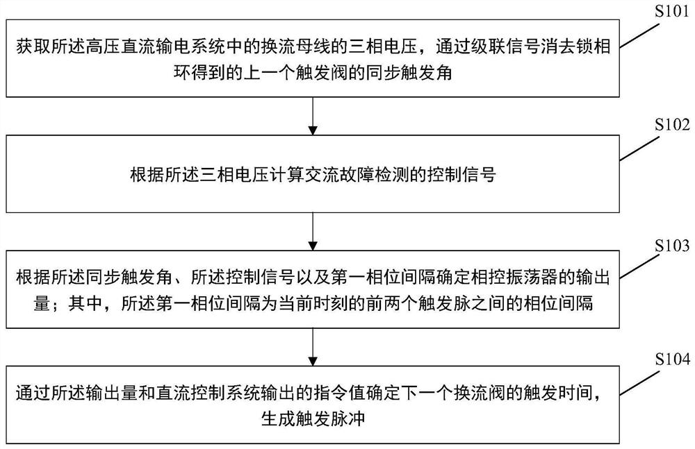
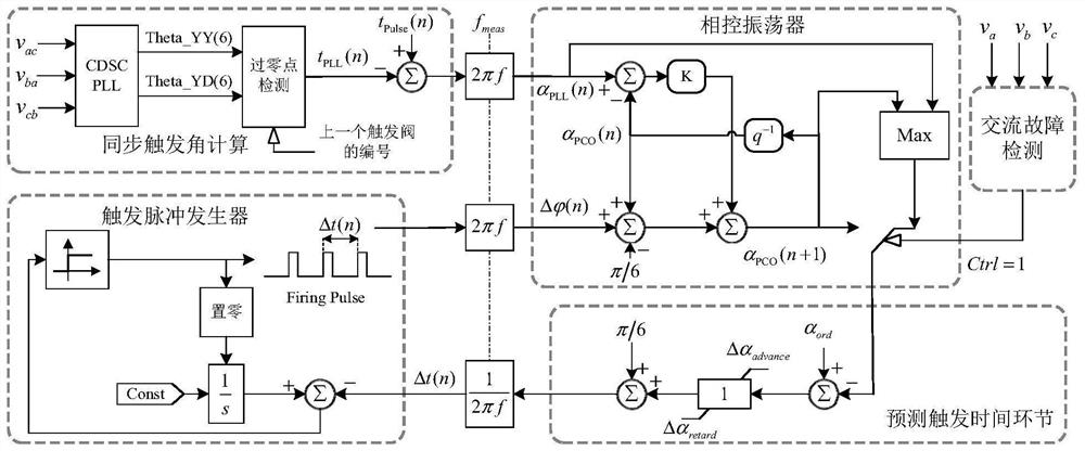
[0070] see figure 1 , is a schematic flowchart of a method for synchronous triggering of a high-voltage direct current system provided in Embodiment 1 of the present invention. see figure 2 , is a block diagram of a synchronous triggering method for a high-voltage direct current system provided in Embodiment 1 of the present invention.

[0071] Embodiment 1 of the present invention provides a synchronous triggering method for a high-voltage direct current system...


PUM


Abstract

The invention discloses a synchronous triggering method of a high-voltage direct-current system, which comprises the following steps: acquiring three-phase voltage of a converter bus in the high-voltage direct-current power transmission system, and eliminating a phase-locked loop through a cascade signal to obtain a synchronous triggering angle of a previous triggering valve; calculating a controlsignal of AC fault detection according to the three-phase voltage; determining the output quantity of a phase-controlled oscillator according to the synchronous trigger angle, the control signal anda first phase interval; wherein the first phase interval is the phase interval between the first two trigger pulses at the current moment; and determining the trigger time of the next converter valveaccording to the output quantity and an instruction value output by the direct current control system, and generating a trigger pulse. The method can achieve the precise triggering of the converter valve under an AC fault, achieves the precise adjustment of a DC control system, and reduces the subsequent commutation failure probability of a high-voltage DC system. The invention further discloses asynchronous triggering system of the high-voltage direct-current system and a storage medium.

Description

technical field [0001] The invention relates to the technical field of high-voltage direct current transmission, in particular to a method, system and storage medium for synchronous triggering of a high-voltage direct current system. Background technique [0002] In the current high-voltage direct current transmission system, the pole control system is the core of the high-voltage direct current transmission system, but the pole control system needs synchronous trigger control as the basis, which is used to change the trigger pulse time of the converter valve, so as to realize the operation status of the entire direct current system. adjust. Synchronous trigger control can be divided into two control methods: split-phase trigger control and equal-phase interval trigger control; among them, the early phase-split trigger control based on zero-crossing detection, due to the dispersion of the control components of each phase and the three-phase Voltage distortion causes unequal...

Claims


Application Information

Patent Timeline
Patent Type & Authority Applications(China)
IPC IPC(8): G01R19/165G01R31/00
CPCG01R19/1658G01R31/00
Inventor 傅闯龚英明魏伟李欢文兆新吴秋媚
Owner ELECTRIC POWER RESEARCH INSTITUTE, CHINA SOUTHERN POWER GRID CO LTD
Why Eureka
Try Eureka