Linear engineering design drawing generation method
A technology of design drawings and engineering drawings, applied in the field of image processing, can solve the problems of not being able to highlight the main body of linear engineering, generating too much useless data in design drawings, etc., and achieve the effects of practical solutions, reduced quantities, and accurate methods
- Summary
- Abstract
- Description
- Claims
- Application Information
AI Technical Summary
Problems solved by technology
Method used
Image

Examples
Embodiment 1
[0056] The idea of the present invention is to cut out the nodes with a large degree of curvature in the linear engineering, then connect the cut nodes into lines, cut the data within the specified distance range around the linear engineering, and then calculate the angle to rotate and translate the data to achieve the linear For the purpose of fixing the project at the center of the design drawing, the design drawing generated by the present invention is relatively long, but the main body information of the linear project is more prominent.
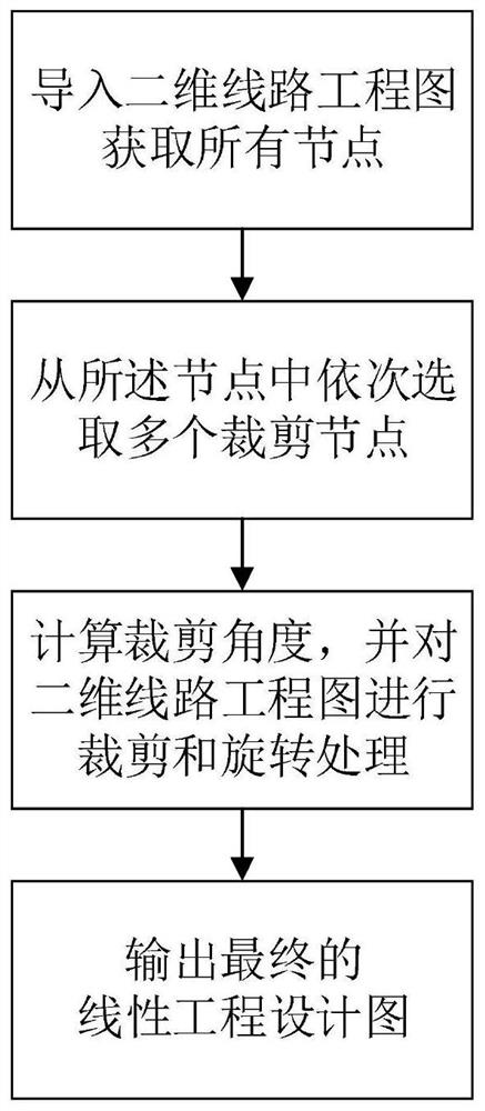
[0057] Such as figure 1 As shown, a linear engineering design drawing generation method, including the following steps:
[0058] a: Import a two-dimensional line engineering drawing to obtain all nodes in the line; the nodes include the initial point and the final point; the line is composed of several nodes;
[0059] b: select a plurality of clipping nodes in sequence among the nodes;
[0060] c: calculating a corresponding clipping...
Embodiment 2
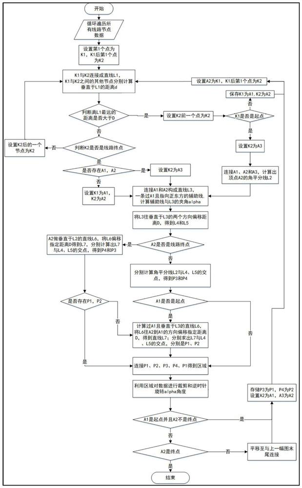
[0066] Such as figure 2 As shown, this embodiment is a detailed technical solution of Embodiment 1, a method for generating a linear engineering design diagram, comprising the following steps:
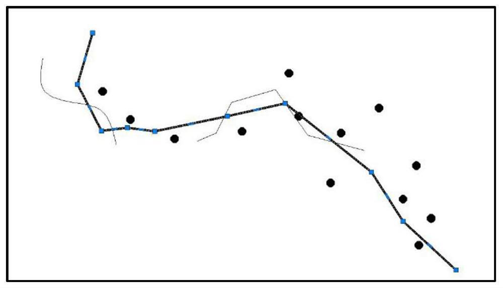
[0067] S1: Get all nodes from the core linear project, such as image 3 shown;
[0068] S2: Set the first node as node K1, and set the first node after node K1 as node K2, such as Figure 4 shown;
[0069] S3: connect the node K1 and the node K2 into a straight line L1, and calculate the distance d perpendicular to the straight line L1 for other nodes between the node K1 and the node K2;
[0070] S4: Determine whether the farthest distance from the straight line L1 is greater than D, if the distance is less than D, enter step S5; otherwise, enter step S6, as Figure 5 shown;
[0071] Among them, if the node K1 is adjacent to the node K2, and there are no other nodes in between, then the distance is 0, within the range D.
[0072] S5: If node K2 is the last node of the line at th...
Embodiment 3
[0094] Such as Figure 24 As shown, a linear engineering design diagram generation device includes at least one processor, and a memory connected to the at least one processor in communication; the memory stores instructions that can be executed by the at least one processor, and the The instructions are executed by the at least one processor, so that the at least one processor can execute the method for generating a linear engineering design diagram described in the foregoing embodiments. The input and output interfaces may include a display, a keyboard, a mouse, and a USB interface for inputting and outputting data; the power supply is used for providing electrical energy for the linear engineering design drawing generation device.
[0095] Those skilled in the art can understand that all or part of the steps for implementing the above-mentioned method embodiments can be completed by hardware related to program instructions, and the aforementioned programs can be stored in c...
PUM
 Abstract
Description
Claims
Application Information
 - R&D
- Intellectual Property
- Life Sciences
- Materials
- Tech Scout
- Unparalleled Data Quality
- Higher Quality Content
- 60% Fewer Hallucinations
Browse by: Latest US Patents, China's latest patents, Technical Efficacy Thesaurus, Application Domain, Technology Topic, Popular Technical Reports.
© 2025 PatSnap. All rights reserved.Legal|Privacy policy|Modern Slavery Act Transparency Statement|Sitemap|About US| Contact US: help@patsnap.com