Power distribution cabinet protection structure with high safety

A protective structure and power distribution cabinet technology, which is applied in substation/power distribution device casing, electrical components, substation/switch layout details, etc., can solve problems such as low safety, people's injury, and damage to electrical components inside the power distribution cabinet. Achieve high safety effect

Inactive Publication Date: 2020-09-11
桐乡宏晨工业设计有限公司
View PDF1 Cites 0 Cited by
  • Summary
  • Abstract
  • Description
  • Claims
  • Application Information

AI Technical Summary

Problems solved by technology

[0006] The heating wire in the heating layer releases heat to heat up the inside of the protective box, so that the moisture inside the protective box is vaporized, and the airflow formed by the operation of the first ventilation fan and the second ventilation fan drives the water vapor to be discharged from the ventilation pipe, which solves the existing distribution problem. The distribution cabinet of the electric cabinet is installed outdoors. In areas with high humidity, the moisture in the distribution box is too large, which is easy to damage the circuit components;
[0007] The airflow formed by the operation of the first ventilation fan and the second ventilation fan reduces the internal temperature of the power distribution cabinet and the protective box to achieve a cooling effect, which solves the problem that the existing power distribution cabinet will generate a large amount of heat when it is

Method used


Image

  • Power distribution cabinet protection structure with high safety
  • Power distribution cabinet protection structure with high safety
  • Power distribution cabinet protection structure with high safety

Examples


Embodiment 1

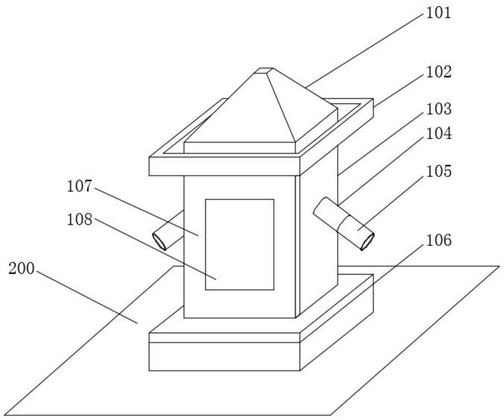
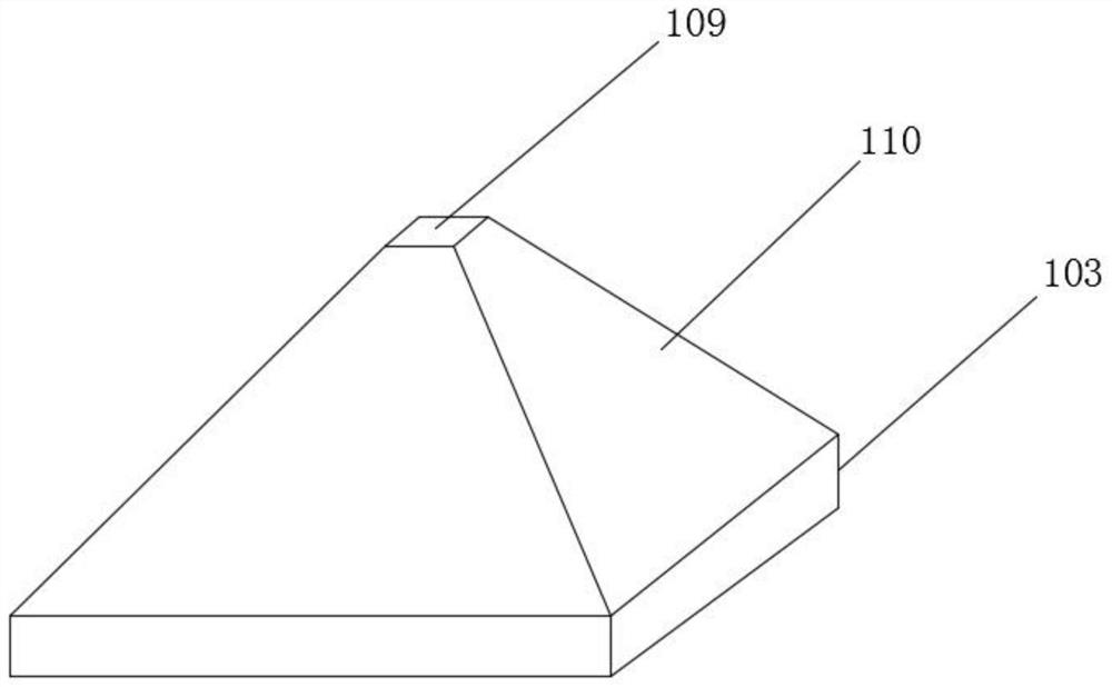
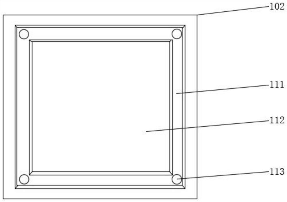
[0048] see Figure 1-9 As shown, this embodiment is a high-safety protection structure for a power distribution cabinet, including an anti-spray cap 101, a protective box 103, and a load-bearing base 106. The top of the protective box 103 is equipped with an anti-spray cap 101, and the protective box A water guide frame 102 is installed outside the top of the body 103. The protective box 103 is installed on the top of the load-bearing base 106. The load-bearing base 106 is installed on the ground 200. Both sides of the protective box 103 are obliquely installed with ventilation pipes 104, and the ventilation pipes 104 The bottom end is connected with a dust-proof pipe 105, and a protective box door 107 is installed on one side of the protective box body 103, and a protective box door 107 is provided with an observation port 108 equipped with tempered glass;

[0049] A heating layer 125 is provided on the inner wall of the protective box 103, and a heating wire is installed in ...


PUM


Abstract

The invention discloses a power distribution cabinet protection structure with high safety. The protection structure comprises a rain-proof cap body, a protection box body and a bearing base, the rain-proof cap body is installed at the top of the protection box body, a water guide frame is installed at the top end of the protection box body in a sleeving mode, the protection box body is installedat the top of the bearing base, the bearing base is installed on the ground, ventilation pipes are installed on the two sides of the protection box body, dustproof pipes are connected to the bottom ends of the ventilation pipes, and a protection box door is installed on one side of the protection box body and is provided with an observation port. A heating layer is arranged in the inner wall of the protection box body, a power distribution cabinet is installed at the bottom of an inner cavity of the protection box body, damping springs are installed between the power distribution cabinet and the protection box body, stand columns are arranged on the two sides of the power distribution cabinet, and multiple transverse columns are installed on one sides of the stand columns. The power distribution cabinet protection structure has the functions of rain prevention, moisture prevention, high temperature prevention, electric leakage prevention, dust prevention and collision prevention, so that the protection effect of the structure is good, the safety is high, the failure frequency of the power distribution cabinet is greatly reduced, and the service life is prolonged.

Description

technical field [0001] The invention relates to the technical field of power distribution cabinet protection, in particular to a high-safety power distribution cabinet protection structure. Background technique [0002] The power distribution cabinet is the general name of the motor control center; the power distribution cabinet is used in the occasions where the load is relatively scattered and there are few circuits; the motor control center is used in the occasions where the load is concentrated and there are many circuits; The electrical energy distributed to the nearest load, this level of equipment should provide protection, monitoring and control of the load. [0003] The patent with the application number CN201610939561.7 discloses a power distribution cabinet, including a cabinet body, a door body and a wiring device; by setting the first installation area and the second installation area in the cabinet, the power distribution equipment is set in the first installat...

Claims


Application Information

Patent Timeline
IPC IPC(8): H02B1/56H02B1/54H02B1/28H02B1/30H02B1/32
CPCH02B1/28H02B1/30H02B1/306H02B1/32H02B1/54H02B1/565
Inventor 周佳斌詹建朝
Owner 桐乡宏晨工业设计有限公司
Why Eureka
Try Eureka