
Floating photovoltaic power station system

A photovoltaic power station, floating technology, applied in the field of photovoltaic systems, can solve the problems of inability to adjust the angle, inconvenient splicing, etc., and achieve the effect of improving practicability and increasing the usable area

Pending Publication Date: 2020-09-11
江苏长欣车辆装备有限公司
View PDF0 Cites 9 Cited by
  • Summary
  • Abstract
  • Description
  • Claims
  • Application Information

AI Technical Summary

Problems solved by technology

[0005] The purpose of the present invention is to provide a floating photovoltaic power plant system, which solves the problems of inability to adjust the angle and inconvenient splicing in the prior art

Method used


Image

  • Floating photovoltaic power station system
  • Floating photovoltaic power station system
  • Floating photovoltaic power station system

Examples


Embodiment Construction

[0031] The following will clearly and completely describe the technical solutions in the embodiments of the present invention with reference to the drawings in the embodiments of the present invention.

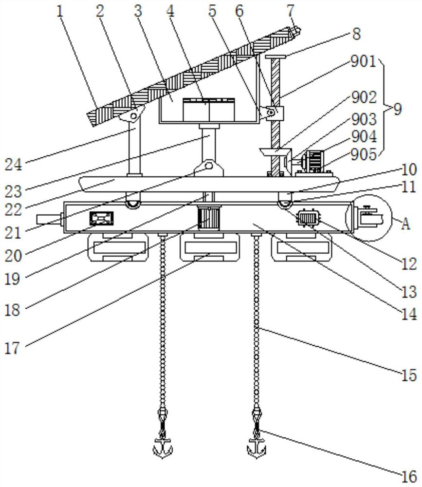
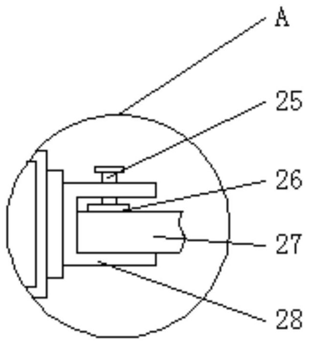
[0032] The present invention provides a technical solution: a floating photovoltaic power station system, including a mounting plate 14, floats 17 are arranged at equal intervals at the bottom of the mounting plate 14, a locking block 27 is fixed on the left end of the mounting plate 14, and a fixing block 27 is fixed on the right end of the mounting plate 14 There is a card slot 28 that matches the card block 27, and the card block 27 is snapped into the inner cavity of the card slot 28 to facilitate the splicing of the system in the horizontal direction (see figure 1 , 2 and 4);

[0033] The front end of the mounting plate 14 is fixed with a reserved block 30, and the rear end of the mounting plate 14 is fixed with a reserved slot 29 that matches the reserved block 30, and ...


PUM


Abstract

The invention discloses a floating type photovoltaic power station system. The system comprises a mounting plate; floaters are arranged at the bottom of the mounting plate at equal intervals; a GPS positioner is mounted at the left end of an inner cavity of the mounting plate; a single-chip microcomputer is mounted at the right end of an inner cavity of the mounting plate; and a driving motor is mounted in the center of an inner cavity of the mounting plate. A photosensitive sensor transmits sensed sunlight information to the GPS positioner, the GPS positioner transmits the received data to the single-chip microcomputer, the single-chip microcomputer controls the driving motor and a servo motor to work, and the driving motor drives a turntable to rotate through a rotating shaft, so a solarphotovoltaic panel can be conveniently adjusted in the horizontal direction; and meanwhile, a rotating mechanism enables a sleeve to move so as to drive a connecting base to rotate, under cooperationof a first connecting block and a second connecting block, the connecting base drives the solar photovoltaic panel at the top of a shell to rotate, and the inclination angle of the solar photovoltaicpanel can be adjusted conveniently, so the solar photovoltaic panel can obtain sufficient illumination conveniently.

Description

technical field [0001] The invention relates to the technical field of photovoltaic systems, in particular to a floating photovoltaic power station system. Background technique [0002] With the continuous progress and development of society, clean energy has begun to be developed and utilized. Solar power generation is an emerging renewable energy source and is the core part of the solar power generation system. Solar photovoltaic panels can convert solar energy into electrical energy that people need. Therefore, it will occupy a large amount of land area. Due to the scarcity of land resources, more users will set it on the water surface, but there are still some shortcomings in the existing system: [0003] Most of the traditional systems are fixed, and the angle of the photovoltaic panels cannot be adjusted. As a result, the area where the photovoltaic panels receive light is limited, which makes the system receive insufficient light. In addition, the traditional systems ...

Claims


Application Information

Patent Timeline
Patent Type & Authority Applications(China)
IPC IPC(8): H02S20/32H02S10/00G05D3/10B63B35/44
CPCB63B35/44B63B2035/4453G05D3/105H02S10/00H02S20/32Y02E10/50
Inventor 张云添王力孙晓梅
Owner 江苏长欣车辆装备有限公司
Learn More