Hydraulic punching machine for flange plate machining

A stamping machine and hydraulic technology, applied in the field of hydraulic stamping machines, can solve problems such as low stamping efficiency, single punch, damage to mechanical parts, etc., to ensure complete stamping, prevent excessive pressure, and improve stamping effects.

Inactive Publication Date: 2020-09-15
喻贞烈
View PDF6 Cites 4 Cited by
  • Summary
  • Abstract
  • Description
  • Claims
  • Application Information

AI Technical Summary

Problems solved by technology

[0003] However, there are still some shortcomings in the stamping process of traditional stamping machines: First, most of the traditional stamping machines are rigid stamping, and the pressure is relatively high. For the production of some precision parts, too fast impact and pressure are easy to damage the machine Parts cause damage, which affects the quality of mechanical parts; secondly, the traditional stamping machine has a single punch (mostly flat head), and can only stamp one type and specification of stamping parts, which seriously wastes the use efficiency of stamping equipment, especially in different processing. When stamping parts of different sizes (such as flange steel sheets with different areas) and stepped parts, it is necessary to manually replace the stamping head, which is not only cumbersome to operate, but also has low stamping efficiency

Method used


Image

  • Hydraulic punching machine for flange plate machining
  • Hydraulic punching machine for flange plate machining
  • Hydraulic punching machine for flange plate machining

Examples


Embodiment Construction

[0019] The following will clearly and completely describe the technical solutions in the embodiments of the present invention with reference to the accompanying drawings in the embodiments of the present invention. Obviously, the described embodiments are only some, not all, embodiments of the present invention. Based on the embodiments of the present invention, all other embodiments obtained by persons of ordinary skill in the art without making creative efforts belong to the protection scope of the present invention.

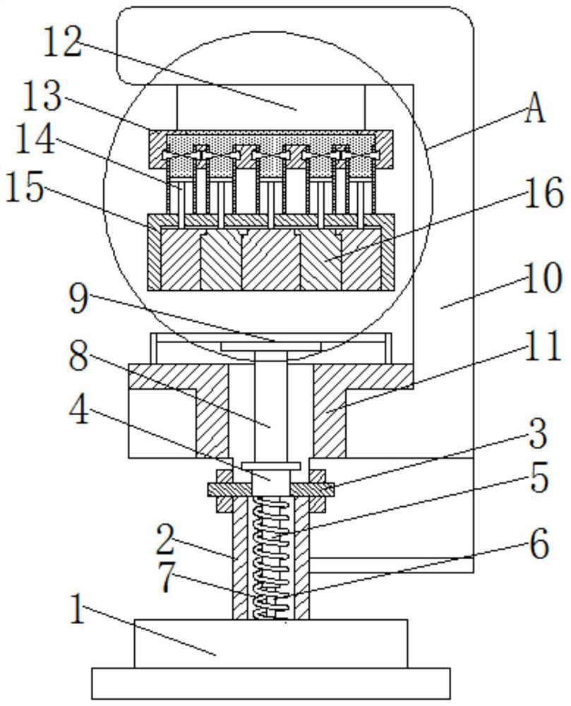
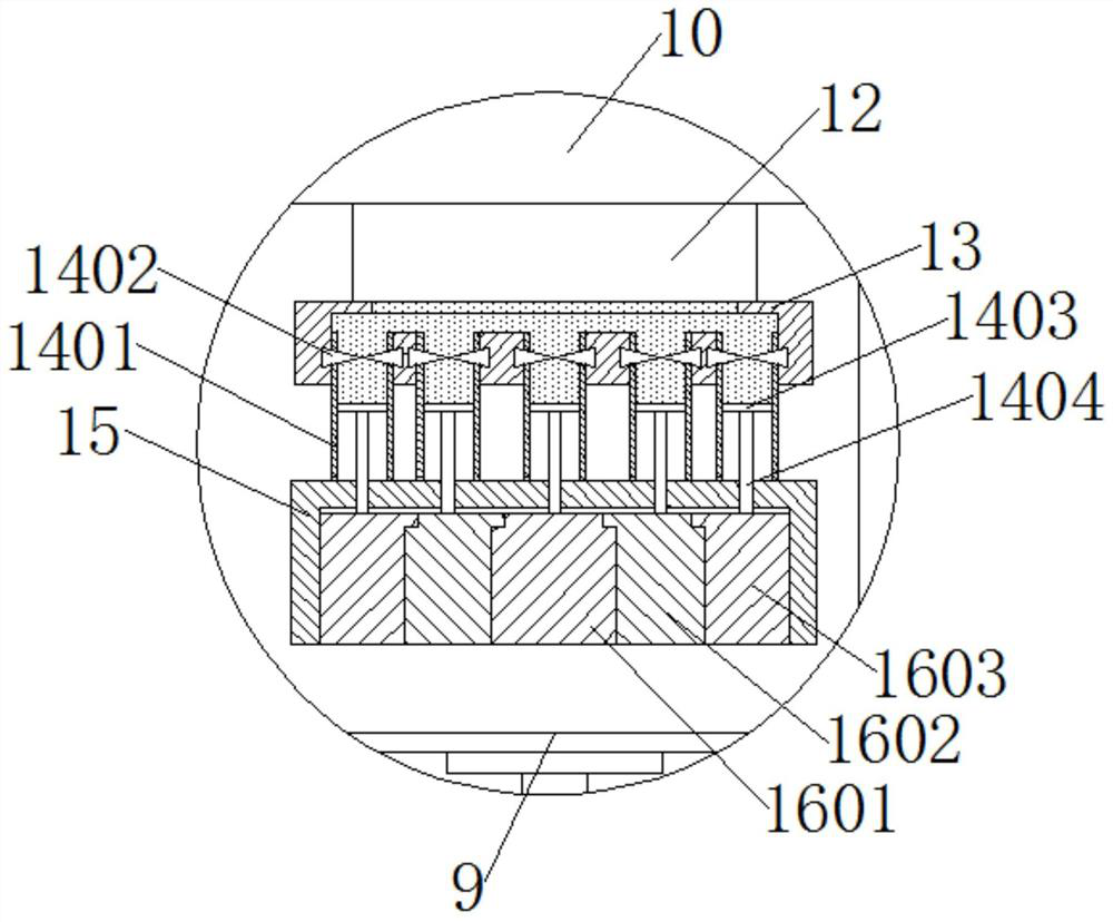
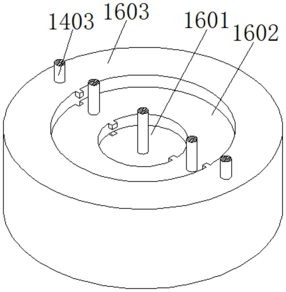
[0020] see Figure 1-5 , a hydraulic stamping machine for flange processing, comprising a base 1, the upper end of the base 1 is fixedly connected with a support 2, the upper end of the support 2 is fixedly connected with a fixed plate 3, and the middle part of the fixed plate 3 is movably sleeved with a sliding rod 4. The bottom of the sliding rod 4 is fixedly connected with the sleeve 5, and the inside of the sleeve 5 is movably socketed with the vertical ro...


PUM


Abstract

The invention relates to the technical field of mechanical equipment, and discloses a hydraulic punching machine for flange plate machining. The hydraulic punching machine comprises a base, the upperend of the base is fixedly connected with a supporting column, the upper end of the supporting column is fixedly connected with a fixing plate, the middle of the fixing plate is movably sleeved with asliding rod, the bottom of the sliding rod is fixedly connected with a sleeve, and a vertical rod fixedly connected with the base is movably sleeved with the sleeve. According to the hydraulic punching machine, through the arrangement of oil distribution pipe fittings and a stamping device, stamping heads of corresponding sizes can be selected for stamping according to switches of opened valves,meanwhile, when an annular stamping part needs to be stamped, only the valves on the two corresponding sides can be opened, and the stamping heads on the two sides can stamp the annular stamping part,so that stamping force can be conveniently increased in a centralized mode, and the stamping effect is improved; and by controlling the opening time difference of all the corresponding valves, all the stamping heads are in a step shape so that people can conveniently stamp and shape stepped parts.

Description

technical field [0001] The invention relates to the technical field of mechanical equipment, in particular to a hydraulic stamping machine for processing flanges. Background technique [0002] Stamping is to apply external force to plates, pipes and profiles by presses and molds to cause plastic deformation or separation, so as to obtain workpieces (stamping parts) of required shape and size. Stamping and forging belong to plastic processing ( or pressure processing), collectively known as forging, stamping blanks are mainly hot-rolled and cold-rolled steel plates and steel strips, and most of them are stamped into finished products in mechanical parts processing plants. [0003] However, there are still some shortcomings in the stamping process of traditional stamping machines: First, most of the traditional stamping machines are rigid stamping, and the pressure is relatively high. Parts cause damage, which affects the quality of mechanical parts; secondly, the traditional...

Claims


Application Information

Patent Timeline
Patent Type & Authority Applications(China)
IPC IPC(8): B21D37/02B21D45/04
CPCB21D37/02B21D45/04
Inventor 喻贞烈
Owner 喻贞烈
Why Eureka
Try Eureka