
Bias-rail type girder automatic welding equipment

An automatic welding, off-track technology, applied in the direction of welding equipment, welding equipment, auxiliary welding equipment, etc., to achieve the effect of easy welding

Inactive Publication Date: 2020-09-15
张雨
View PDF7 Cites 2 Cited by
  • Summary
  • Abstract
  • Description
  • Claims
  • Application Information

AI Technical Summary

Problems solved by technology

[0005] In order to solve the above technical problems, an automatic welding equipment for off-track girders is provided. This technical solution solves the problem of automatic welding of off-track girder tracks

Method used


Image

  • Bias-rail type girder automatic welding equipment
  • Bias-rail type girder automatic welding equipment
  • Bias-rail type girder automatic welding equipment

Examples


Embodiment Construction

[0042] The following description serves to disclose the present invention to enable those skilled in the art to carry out the present invention. The preferred embodiments described below are only examples, and those skilled in the art can devise other obvious variations.

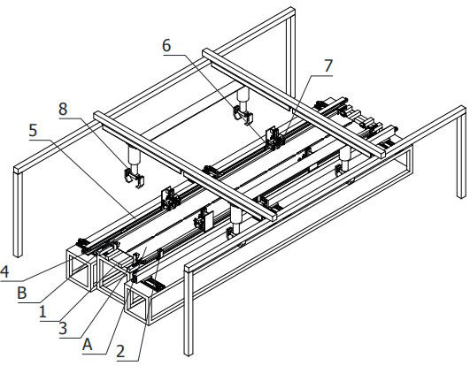
[0043] refer to figure 1 as shown,

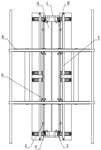
[0044] An off-track girder automatic welding equipment, which is used to horizontally weld the track B on both sides of the top of the girder prefabricated panel A. The welding equipment includes:

[0045] Place rack 1;

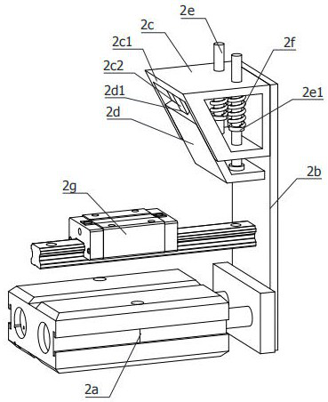
[0046] At least three side elastic locators 2 and at least two end elastic locators 3, the side elastic locators 2 are spaced on both sides of the placement frame 1, and in the working state, the working ends of the side elastic locators 2 are relatively abutted On both sides of the girder prefabricated panel A, the end face elastic locators 3 are arranged at both ends of the placement frame 1 at equal intervals, and in the working state, the working ...


PUM


Abstract

The invention relates to the technical field of automatic welding, in particular to bias-rail type girder automatic welding equipment which is applied to horizontally welding rails to the two sides ofthe top end of a girder prefabricated panel. The welding equipment comprises a placing frame, at least three side surface elastic positioners, at least two end surface elastic positioners, rail end surface clamping positioners, dual-station two-way moving sliders, elastic dual-wheel resisters, a dual-station welding frame and a dual-station suspension portal frame, wherein the side surface elastic positioners are arranged at the two sides of the placing frame in a spaced mode; the rail end surface clamping positioners are arranged on four corners of the top end of the placing frame; the dual-station two-way moving sliders are horizontally arranged at the two sides of the placing frame; the working ends of the elastic dual-wheel resisters are vertically downwards arranged on dual working ends; dual working ends of the dual-station welding frame are arranged between the dual working ends of the elastic dual-wheel resisters in an inclined mode towards the two side surface of a rail welding surface; and the dual-station suspension portal frame is placed at the top end of the placing frame. The equipment can automatically position a prefabricated panel, can automatically weld the rail,and is high in work efficiency.

Description

technical field [0001] The invention relates to the technical field of automatic welding, in particular to an off-track automatic welding equipment for girders. Background technique [0002] The tire crane belongs to the category of hoisting machinery. There are many types of rails for the girder of the tire crane. The welded trolley rails include square steel rails, P43 rails, and A75A rails. When welding the rails and the girder panels, welding deformation will occur. To reduce welding deformation, the welding process of the track is also continuously improved and perfected, and various preparation processes before production must also be improved and updated accordingly. The off-track girder of the tire crane, because the track is installed on one side of the girder panel, in the past, when the single panel was welded to the track, it is easy to shrink and deform to the side of the track, which has a great impact on the later box forming . [0003] Chinese patent CN2016...

Claims


Application Information

Patent Timeline
Patent Type & Authority Applications(China)
IPC IPC(8): B23K31/02B23K37/04
CPCB23K31/02B23K37/0443
Inventor 张雨
Owner 张雨
Learn More