Punching and forming integrated device and implementation method thereof
A hole forming and integrated technology, applied in binding, metal processing, etc., can solve problems such as unstable binding quality and hole position deviation, and achieve the effect of reducing the risk of hole position deviation
- Summary
- Abstract
- Description
- Claims
- Application Information
AI Technical Summary
Problems solved by technology
Method used
Image
Examples
Embodiment 1
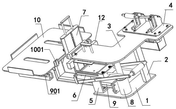
[0041] refer to figure 1 and Figure 9As shown, one embodiment of the present invention is a punching and forming integrated device, including a supporting base 1, wherein the supporting base 1 is the stress point of the entire device, and the supporting base 1 can be fixed on a desktop or other frame. A first column 2 is provided on the bearing base 1 , and an installation platform 3 is provided on the first column 2 . A sufficient gap is left between the bearing base 1 and the installation platform 3 through the first column 2 .
[0042] The head end of the above-mentioned installation platform 3 is provided with a punching mechanism 4, wherein the punching mechanism 4 can be an existing punching device, the above-mentioned bearing base plate 1 is provided with a second column 5, and the above-mentioned second column 5 is provided with a needle clamping mechanism 6. Its clamping mechanism 7 outputs the clamping piece, and its clamping piece is an existing commodity, and the...
Embodiment 2
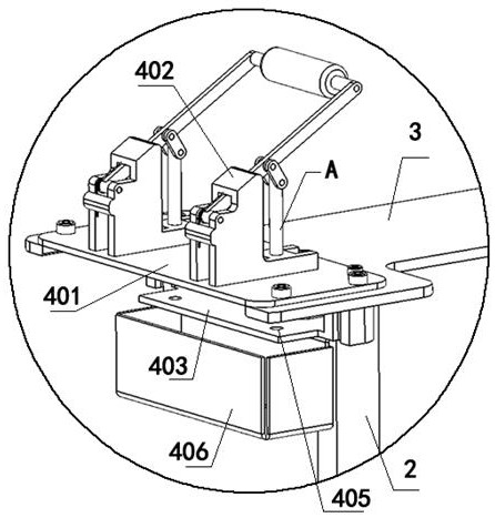
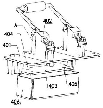
[0049] Based on the above examples, refer to figure 2 , image 3 As shown, one embodiment of the present invention is that the above-mentioned punching mechanism 4 includes a punching mounting plate 401, which is provided with a plurality of screw holes on the punching mounting plate 401, and the whole punching mechanism 4 is fixed by the punching mounting plate 401. On the installation platform 3, the above-mentioned punching installation plate 401 is provided with a puncher 402, wherein the puncher 402 is an existing commodity, and its puncher 402 has a punching needle A, and the pair of punching needles A is pressed down by the handle. The paper is punched.
[0050] The above-mentioned punching installation plate 401 is provided with a drill hole, and the drill hole corresponds to the puncher 402, that is, the moving path of the punching needle A of the puncher 402 matches the drill hole, and when the puncher 402 is pressed down, the punching The hole needle A acts on th...
Embodiment 3
[0056] Based on the above examples, refer to Figure 4 As shown, one embodiment of the present invention is that the above-mentioned needle clamp mechanism 6 includes a needle clamp box 601, which has a storage groove on the needle clamp box 601, and the end of the storage groove is open, and the head end of the above-mentioned needle clamp box 601 is provided with a push plate 602 Arrange and place the needles B in the storage groove of the needle box 601, and push the needles B to the end of the storage groove through the push plate 602. The end of the needle box 601 is provided with a lifting plate 603, wherein the lifting plate 603 is connected with the clamping The size of the bottom of the needle B matches. The lower end of the above-mentioned lifting plate 603 is provided with a lever mechanism 604. One side of the above-mentioned lifting plate 603 is provided with a baffle plate 605, which is used to place the clamped needle by the clamping box 601, and is used to place...
PUM
 Abstract
Description
Claims
Application Information
 - R&D
- Intellectual Property
- Life Sciences
- Materials
- Tech Scout
- Unparalleled Data Quality
- Higher Quality Content
- 60% Fewer Hallucinations
Browse by: Latest US Patents, China's latest patents, Technical Efficacy Thesaurus, Application Domain, Technology Topic, Popular Technical Reports.
© 2025 PatSnap. All rights reserved.Legal|Privacy policy|Modern Slavery Act Transparency Statement|Sitemap|About US| Contact US: help@patsnap.com


