Hole-forming integrated device and implementation method thereof

A hole forming and integrated technology, applied in binding, metal processing, etc., can solve the problems of unstable binding quality, hole position deviation, etc., and achieve the effect of reducing the risk of hole position deviation

Active Publication Date: 2021-02-05
SICHUAN UNIV
View PDF7 Cites 0 Cited by
  • Summary
  • Abstract
  • Description
  • Claims
  • Application Information

AI Technical Summary

Problems solved by technology

[0005] The purpose of the present invention is to provide an integrated device for punching and forming and its implementation method, in order to optimize the existing paper binding process, the hole position deviation often occurs, resulting in the problem of unstable binding quality

Method used


Image

  • Hole-forming integrated device and implementation method thereof
  • Hole-forming integrated device and implementation method thereof
  • Hole-forming integrated device and implementation method thereof

Examples


Embodiment 1

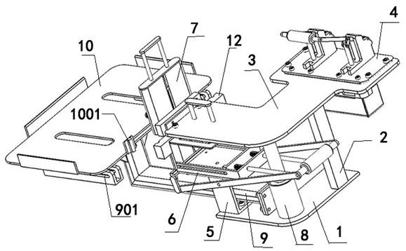
[0041] refer to figure 1 and Figure 9As shown, one embodiment of the present invention is a punching and forming integrated device, including a supporting base 1, wherein the supporting base 1 is the stress point of the entire device, and the supporting base 1 can be fixed on a desktop or other frame. A first column 2 is provided on the bearing base 1 , and an installation platform 3 is provided on the first column 2 . A sufficient gap is left between the bearing base 1 and the installation platform 3 through the first column 2 .

[0042] The head end of the above-mentioned installation platform 3 is provided with a punching mechanism 4, wherein the punching mechanism 4 can be an existing punching device, the above-mentioned bearing base plate 1 is provided with a second column 5, and the above-mentioned second column 5 is provided with a needle clamping mechanism 6. Its clamping mechanism 7 outputs the clamping piece, and its clamping piece is an existing commodity, and the...

Embodiment 2

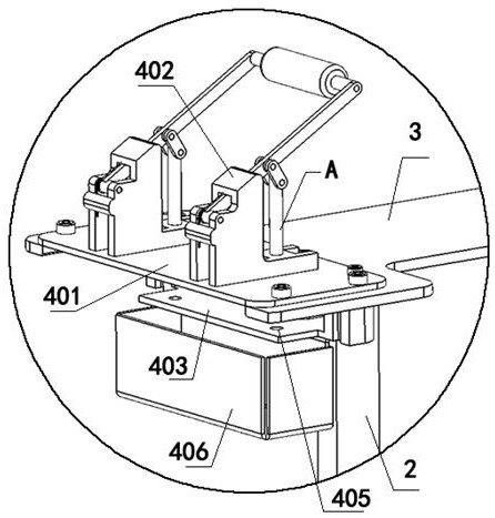
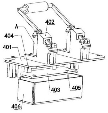
[0049] Based on the above examples, refer to figure 2 , image 3 As shown, one embodiment of the present invention is that the above-mentioned punching mechanism 4 includes a punching mounting plate 401, which is provided with a plurality of screw holes on the punching mounting plate 401, and the whole punching mechanism 4 is fixed by the punching mounting plate 401. On the installation platform 3, the above-mentioned punching installation plate 401 is provided with a puncher 402, wherein the puncher 402 is an existing commodity, and its puncher 402 has a punching needle A, and the pair of punching needles A is pressed down by the handle. The paper is punched.

[0050] The above-mentioned punching installation plate 401 is provided with a drill hole, and the drill hole corresponds to the puncher 402, that is, the moving path of the punching needle A of the puncher 402 matches the drill hole, and when the puncher 402 is pressed down, the punching The hole needle A acts on th...

Embodiment 3

[0056] Based on the above examples, refer to Figure 4 As shown, one embodiment of the present invention is that the above-mentioned needle clamp mechanism 6 includes a needle clamp box 601, which has a storage groove on the needle clamp box 601, and the end of the storage groove is open, and the head end of the above-mentioned needle clamp box 601 is provided with a push plate 602 Arrange and place the needles B in the storage groove of the needle box 601, and push the needles B to the end of the storage groove through the push plate 602. The end of the needle box 601 is provided with a lifting plate 603, wherein the lifting plate 603 is connected with the clamping The size of the bottom of the needle B is consistent, the lower end of the lifting plate 603 is provided with a lever mechanism 604, the side of the lifting plate 603 is provided with a baffle 605, the needle clamping box 601 places the clamping needle, and the pushing plate 602 pushes the clamping needle to the lif...


PUM


Abstract

The invention discloses an integrated device for punching and forming and an implementation method thereof, comprising a bearing base plate, a first column is arranged on the bearing plate, an installation platform is arranged on the first column, and a punching mechanism is arranged at the head end of the installation platform , the above-mentioned bearing bottom plate is provided with a second column, the above-mentioned second column is provided with a pin-clamping mechanism, the end of the above-mentioned mounting platform is installed with a clip mechanism corresponding to the needle-clamping mechanism, and a rotating support is provided between the above-mentioned bearing bottom plate and the mounting platform, The movable end of the rotating support is provided with a cantilever, the end of the cantilever is provided with a slide rail, and the slide rail is provided with a pallet, in order to optimize the existing paper binding process, the hole position deviation often occurs, resulting in unstable binding quality.

Description

technical field [0001] The invention relates to office paper binding, in particular to a punching and forming integrated device and an implementation method thereof. Background technique [0002] With the progress of the times, the current society is basically in the paperless office of the Internet to promote environmental protection. However, due to certain risk factors in the network environment, important files that need to be recorded are usually not saved on the Internet. Instead, the content is converted into paper by the printer, and the paper is used as the main body of the record. Since the printer is widely used, it is one of the output devices of the computer. It can print the computer processing results on the relevant paper. Since the printed content is relatively large, the paper needs to be sorted uniformly and bound into a book. For example, legal documents, securities documents, financial documents, etc. [0003] In the actual binding process, the paper n...

Claims


Application Information

Patent Timeline
Patent Type & Authority Patents(China)
IPC IPC(8): B26F1/24B26D7/18B26D7/27B42B5/00B42B5/02
CPCB26D7/18B26D7/27B26F1/24B42B5/00B42B5/02
Inventor 李文强李姗密乐刘启虞胡博
Owner SICHUAN UNIV
Why Eureka
Try Eureka