An exhaust manifold thermal stress evaluation device and method

A technology of exhaust manifold and evaluation device, applied in measurement device, measurement force, material thermal analysis, etc., can solve the problem of high test cost

Active Publication Date: 2021-05-11
DONGFENG COMML VEHICLE CO LTD
View PDF14 Cites 0 Cited by
  • Summary
  • Abstract
  • Description
  • Claims
  • Application Information

AI Technical Summary

Problems solved by technology

[0005] In view of the defects existing in the prior art, the object of the present invention is to provide an exhaust manifold thermal stress evaluation device and method, which can solve the problem of high test cost in the prior art when testing the thermal stress of the engine exhaust manifold

Method used


Image

  • An exhaust manifold thermal stress evaluation device and method
  • An exhaust manifold thermal stress evaluation device and method
  • An exhaust manifold thermal stress evaluation device and method

Examples


Embodiment Construction

[0040] In order to make the purposes, technical solutions and advantages of the embodiments of the present application clearer, the technical solutions in the embodiments of the present application will be clearly and completely described below in conjunction with the drawings in the embodiments of the present application. Obviously, the described embodiments It is a part of the embodiments of this application, but not all of them. Based on the embodiments in the present application, all other embodiments obtained by persons of ordinary skill in the art without making creative efforts belong to the protection scope of the present application.

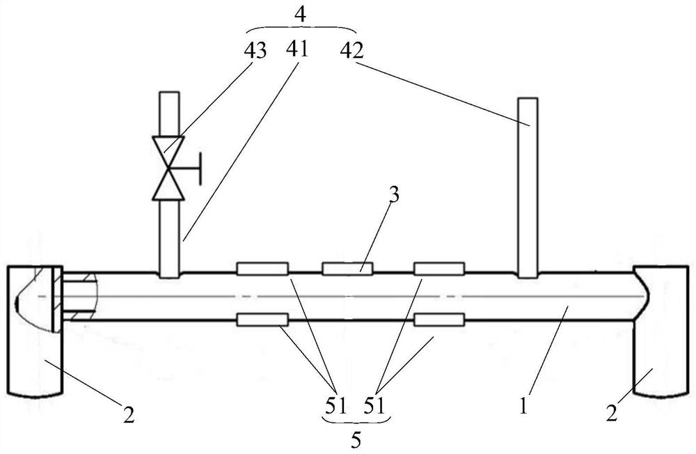
[0041] Embodiments of the present invention will be described in further detail below in conjunction with the accompanying drawings. figure 1 It is a structural schematic diagram of an exhaust manifold thermal stress evaluation device in an embodiment of the present invention, as figure 1 As shown, the present invention provides an exh...


PUM


Abstract

The present invention relates to the technical field of automobile engine testing, in particular to an exhaust manifold thermal stress evaluation device and method, the method comprising the following steps: installing the evaluation device to the exhaust manifold of the first scheme, operating the engine to the test condition, Open the water supply and drainage device to cool down the force measuring rod, use the temperature sensor and the stress detection device to obtain the first strain at the set uniform temperature of the force measuring rod; install the device to the exhaust manifold of the second plan, open the water supply and drainage device to measure the force Rod cooling, use the temperature sensor and stress detection device to obtain the second strain at the set uniform temperature of the load cell; if the first strain is greater than the second strain, the thermal stress level of the exhaust manifold of the first scheme is better than that of the exhaust manifold of the second scheme. Gas manifold thermal stress level. By applying the force measurement of the general strain gauge under the condition of lower temperature and indirectly reflecting the comparison of the stress level of the high-temperature exhaust manifold, the problem of high test cost in the thermal stress test of the engine exhaust manifold in the prior art is solved.

Description

technical field [0001] The invention relates to the technical field of automobile engine testing, in particular to an exhaust manifold thermal stress evaluation device and method. Background technique [0002] In the development of engine exhaust manifolds, thermal deformation and thermal stress cracking are common faults. Usually, the fault problems are solved by adjusting and optimizing materials and structural forms. For this reason, it is often necessary to compare the thermal stress levels of exhaust manifolds of different designs. Differences, so as to provide a basis for design improvement trend judgment. [0003] Engine exhaust manifold thermal stress test is an effective way to evaluate thermal stress. High temperature strain measurement technology, such as high temperature strain gauge, is widely used in the industry. The exhaust manifold temperature field simulation model is corrected by measuring point stress test results, and the thermal load is simulated under...

Claims


Application Information

Patent Timeline
Patent Type & Authority Patents(China)
IPC IPC(8): G01L1/00G01N25/00
CPCG01L1/00G01N25/00
Inventor 邹利亚李智周泉钢张晓红张雷余培吴金柱
Owner DONGFENG COMML VEHICLE CO LTD
Why Eureka
Try Eureka