Supercharge Your Innovation With Domain-Expert AI Agents!

Detection device and detection method

A technology of detection equipment and detection methods, applied in measurement devices, optical testing flaws/defects, instruments, etc., can solve problems such as defocusing phenomenon, limit the accuracy of wafer defect detection equipment, height deviation, etc., to reduce errors, The effect of reducing defocus and increasing precision

Pending Publication Date: 2020-09-15
SKYVERSE TECH CO LTD
View PDF0 Cites 1 Cited by
  • Summary
  • Abstract
  • Description
  • Claims
  • Application Information

AI Technical Summary

Problems solved by technology

In addition, when the electric moving platform drives the wafer to move, it may also introduce a height offset, resulting in an out-of-focus state
Even if the wafer height has been adjusted to focus at the beginning of the scanning inspection, there is still defocus at other inspection positions, which limits the accuracy of the wafer defect inspection equipment

Method used


Image

  • Detection device and detection method
  • Detection device and detection method
  • Detection device and detection method

Examples


Embodiment Construction

[0039] There are many problems in the detection equipment and detection method, for example: in the detection process, it is easy to appear out of focus, resulting in low detection accuracy.

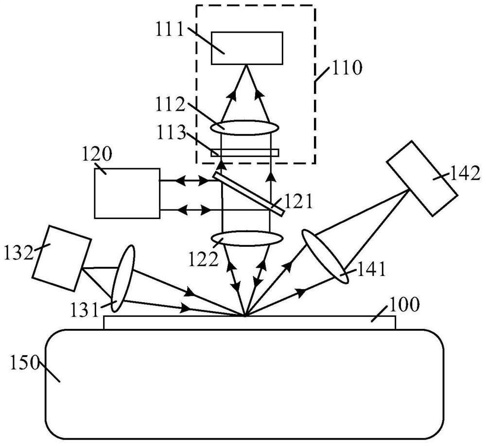
[0040]In order to solve the above technical problem, the present invention provides a detection device, including: a detection system, including: a first detection light source, used to emit the first detection light to the first detection area of ​​the object to be tested; a detection device, used to receive the detected The first detection light returned by the first detection area; the defocus measurement system is used to measure the defocus degree of the object under test relative to the detection system, including: the second detection light source is used to emit light to the second detection area of ​​the object under test second detection light; a receiving component, configured to receive the second detection light returned through the second detection area, and acquire the defo...


PUM


Abstract

The invention provides a detection device and a detection method, and the device comprises a first detection light source which is used for transmitting first detection light to a first detection region of a to-be-detected object; a detection device used for receiving the first detection light returned by the first detection region; an out-of-focus measurement system used for measuring the out-of-focus degree of the to-be-measured object relative to a detection system and comprising a second detection light source used for emitting second detection light to a second detection region of the to-be-measured object; a receiving assembly used for receiving the second detection light returned by the second detection region and obtaining the defocusing power of the second detection region according to the returned second detection light, wherein the second detection region at least partially coincides with the first detection region; and an adjusting device used for adjusting the relative position relation between the to-be-detected object and the detection system according to the defocusing power. According to the detection system, the precision of a detection result can be improved.

Description

technical field [0001] The invention relates to the technical field of semiconductor equipment, in particular to a detection device and a detection method. Background technique [0002] Optical inspection is a general term for detection methods that utilize the interaction between light and chips, among which light scattering method is one of the most important optical inspection methods. Presence and size. Optical detection has the characteristics of fast detection speed and no additional pollution, and is the best solution for on-line detection of chips. [0003] The detection accuracy of optical detection equipment is affected by the defocus of the optical path. The light source, illumination shaping mirror group, wafer surface, signal collection mirror group, and detector in the second detection optical path can collect the strongest scattered signal light when they meet a certain positional relationship. , the situation that satisfies this positional relationship can ...

Claims


Application Information

Patent Timeline
IPC IPC(8): G01N21/95G01B11/06G01B11/30
CPCG01N21/9501G01B11/0625G01B11/30
Inventor 陈鲁黄有为崔高增
Owner SKYVERSE TECH CO LTD
Features
  • R&D
  • Intellectual Property
  • Life Sciences
  • Materials
  • Tech Scout
  • Unparalleled Data Quality
  • Higher Quality Content
  • 60% Fewer Hallucinations
Learn More