An optical path system that improves the shape of the spot and automatically adjusts the size of the spot

An automatic adjustment and optical path system technology, applied in optics, optical components, instruments, etc., can solve the problems of low transmittance and reflectivity of lenses, blurred borders of image spots at overlaps, etc., to eliminate spherical aberration and solve the problem of too long optical path , The target spot is clean and clear

Active Publication Date: 2016-06-01
ZHEJIANG WINSIGHT MEDICAL LASER TECH
View PDF6 Cites 0 Cited by
  • Summary
  • Abstract
  • Description
  • Claims
  • Application Information

AI Technical Summary

Problems solved by technology

Since the wavelength band used is in the deep ultraviolet region, the transmittance and reflectivity of specially coated lenses in this band are relatively low, so it is very important to minimize the use of lenses and ensure the efficiency of energy transmission
[0003] Generally, a double-mirror structure is adopted, such as a double-aspheric mirror structure and a double-mirror structure, which can theoretically perform arbitrary wavefront transformation, but the devices used must be specially designed and customized; and the method of using array microlenses plus plano-convex lenses, although it can be effective Realize shaping, but because of the spherical aberration of the lens, the imaging of each micro-lens is defocused, making the boundary of the overlapping image spot blurred, and the length of the optical path outside the excimer therapeutic instrument is usually longer than 1m. If the focal length of the lens is too large, the defocusing phenomenon will be more serious obvious

Method used


Image

  • An optical path system that improves the shape of the spot and automatically adjusts the size of the spot
  • An optical path system that improves the shape of the spot and automatically adjusts the size of the spot
  • An optical path system that improves the shape of the spot and automatically adjusts the size of the spot

Examples


Embodiment Construction

[0016] Embodiments of the present invention will be further described below in conjunction with accompanying drawings:

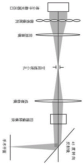
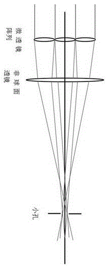
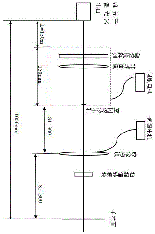
[0017] Such as figure 1 and image 3 As shown, an optical path system that improves the spot shape and automatically adjusts the spot size, which includes a microlens array, an aspheric mirror, a spatial filter aperture, an imaging objective lens, and a scanning deflection module sequentially arranged at the exit of the excimer laser. The scanning deflection module utilizes high-speed If the motor drives multiple mirrors to deflect the laser beam, the scanning deflection module can also directly use the laser beam deflection device, and the microlens array, aspheric mirror and spatial filter aperture constitute a shaping and uniform light device with an integrated box structure, and It translates between the excimer laser exit and the imaging objective lens through the transmission device, and the imaging objective lens moves in parallel according to the co...


PUM


Abstract

The invention relates to a light path system capable of improving light spot patterns and automatically adjusting light spot size. The light path system capable of improving the light spot patterns and automatically adjusting the light spot size comprises a microlens array, an aspheric lens, a spatial filtering aperture, an imaging object lens and a scanning deflection module which are arranged on an excimer laser outlet in sequence. A shaping dodging device of an integrated box structure is formed by the microlens array, the aspheric lens and the spatial filtering aperture and moves horizontally between the excimer laser outlet and the imaging object lens, and the imaging object lens moves in parallel according to the horizontal moving distances of the microlens array, the aspheric lens and the spatial filtering aperture and according to the conjugation ratio calculated according to focal distances. The aspheric lens is adopted, spherical aberration is eliminated greatly, and the defocus of microlens imaging is weakened accordingly. Through the adoption of a secondary focusing method in a light path, the problems of the excessive-length of the light path, spatial filtering and image spot adjustability are solved, target light spots are clean and clear, and round light spots of any size within a certain range can be obtained according to the needs of surgery.

Description

technical field [0001] The invention relates to a design method of an external optical path, belonging to the field of optical path design. It can be applied to the external optical path design of the excimer laser, and can also be applied to the external optical path design based on the industrial processing of the single transverse mode laser. Background technique [0002] Excimer lasers are pulsed laser sources that emit deep ultraviolet light. The output size is typically a rectangular beam with a Gaussian intensity profile. On the surgical surface, a circular spot with relatively uniform energy distribution at each point needs to be obtained, so the optical path must have the functions of spot shaping and uniform energy. At the same time, because the bandwidth of the excimer light source is quite wide, dispersion occurs after being refracted by multiple mirrors, and finally a lot of stray light is generated around the target spot, so the function of spatial filtering ...

Claims


Application Information

Patent Timeline
Patent Type & Authority Patents(China)
IPC IPC(8): G02B27/09
Inventor 陈浩刘党会李红波陈昆仑
Owner ZHEJIANG WINSIGHT MEDICAL LASER TECH
Why Eureka
Try Eureka