Lens apparatus, image capturing apparatus, camera system, determination method of correction value and storage medium

a technology of image capturing apparatus and determination method, which is applied in the field of lens apparatus, image capturing apparatus, determination method of correction value, and storage medium, can solve problems such as cost increase, and achieve the effect of reducing defocus

Active Publication Date: 2021-02-09
CANON KK
View PDF3 Cites 0 Cited by
  • Summary
  • Abstract
  • Description
  • Claims
  • Application Information

AI Technical Summary

Benefits of technology

[0006]The present invention provides a lens apparatus, an image capturing apparatus, a camera system, a correction value determination method, and a storage medium capable of reducing defocus when an extender is attached.

Problems solved by technology

To prevent this, the lens apparatus or the image capturing apparatus may store the focus correction value when the extender is attached, but a measuring equipment to measure the manufacturing error for each apparatus is required, and cost increases.

Method used


Image

  • Lens apparatus, image capturing apparatus, camera system, determination method of correction value and storage medium
  • Lens apparatus, image capturing apparatus, camera system, determination method of correction value and storage medium
  • Lens apparatus, image capturing apparatus, camera system, determination method of correction value and storage medium

Examples


first embodiment

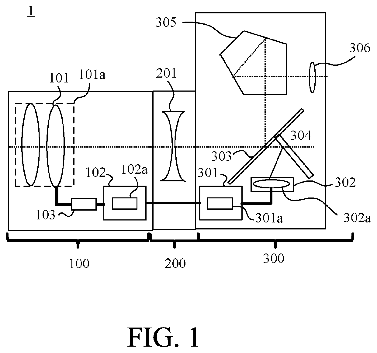
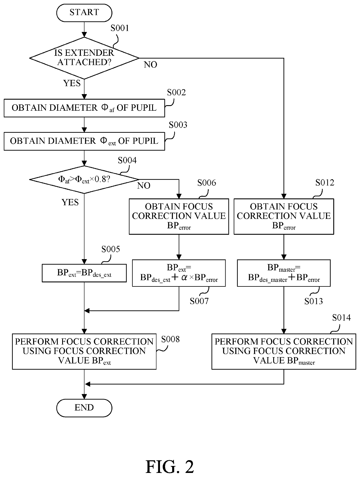
[0031]Referring to FIG. 2, a description will be given of a determination method of the focus correction value when the extender 200 is attached between the lens apparatus 100 and the image capturing apparatus 300. FIG. 2 is a flowchart of a correction value determination method according to this embodiment executed by the lens controller 102.

[0032]In the step S001, the lens controller 102 determines whether or not the extender 200 is attached to the lens apparatus 100 which is attached to the image capturing apparatus 300. When the extender 200 is attached, the flow moves to the step 002, and when the extender 200 is not attached, the flow moves to the step S012.

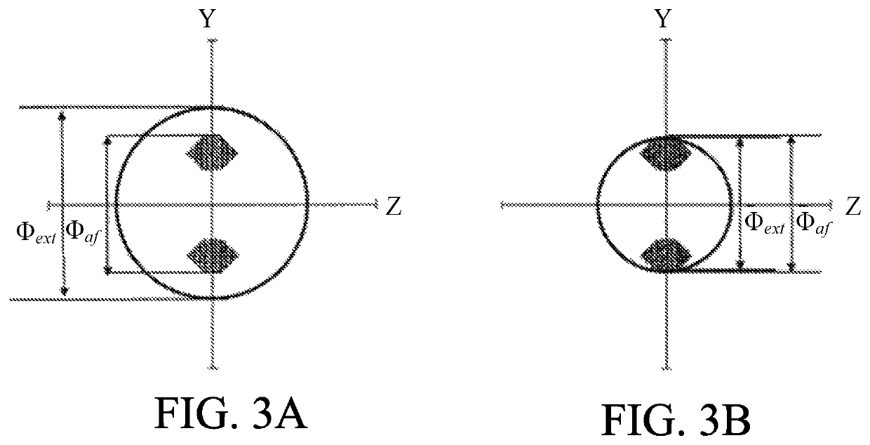
[0033]In the step S002, the lens controller 102 obtains the diameter Φaf of the pupil of the focus detection optical system 302a (the diameter of the circumcircle of the AF pupil through which the AF light flux used for the focus detection process by the phase detection AF system 302 passes) from the camera controller 301.

[...

second embodiment

[0052]Referring to FIG. 4, a description will be given of a determination method of the focus correction value when the extender 200 is attached between the lens apparatus 100 and the image capturing apparatus 300. FIG. 4 is a flowchart of a correction value determination method according to this embodiment executed by the lens controller 102.

[0053]In the step S101, the lens controller 102 determines whether or not the extender 200 is attached to the lens apparatus 100 which is attached to the image capturing apparatus 300. When the extender 200 is attached, the flow moves to the step 102, and when the extender 200 is not attached, the flow moves to the step S112.

[0054]In the step S102, the lens controller 102 obtains F-number Faf which is information regarding the diameter of the pupil of the focus detection optical system 302a from the camera controller 301. The F-number Faf is calculated based on the circumcircle of the AF pupil through which the AF light flux used for the focus ...

third embodiment

[0071]Referring to FIG. 6, a description will be given of a determination method of the focus correction value when the extender 200 is attached between the lens apparatus 100 and the image capturing apparatus 300. FIG. 6 is a flowchart of a correction value determination method according to this embodiment executed by the lens controller 102.

[0072]Processes from the step S201 to the step S204 are respectively the same as the processes from the step S001 to the step S004 in FIG. 2 and thus a detailed description thereof will be omitted.

[0073]In the step S205, the lens controller 102 obtains a focus correction value BPerror based on a manufacturing error when only the lens apparatus 100 is attached from the memory 102a.

[0074]In the step S206, the lens controller 102 calculates a focus correction value BPext using the following expression (5) and transmits the calculated focus correction value BPext to the camera controller 301.

BPext=BPdes_ext+α2×BPerror  (5)

[0075]The coefficient α2 ...


PUM


Abstract

A lens apparatus detachably attachable to an image capturing apparatus including a focus detection unit having a focus detection optical system and performing focus detection process, and a controller controlling driving of a focusing lens unit based on a result of the focus detection process, via an extender including an extender optical system, includes an image capturing optical system including the focusing lens unit, and a determination unit determining a first correction value used for correcting the result of the focus detection process. When the lens apparatus is attached to the image capturing apparatus via the extender, the determination unit determines the first correction value using first information regarding a diameter of a pupil of the focus detection optical system and second information regarding a diameter of a pupil of an optical system including the image capturing optical system and the extender optical system.

Description

BACKGROUND OF THE INVENTIONField of the Invention[0001]The present invention relates to a lens apparatus, an image capturing apparatus, a camera system, a determination method of a correction value, and a storage medium.Description of the Related Art[0002]A method for improving accuracy of autofocus (hereinafter referred to as AF) by a phase detection when an extender (rear conversion lens) is used has been proposed. Japanese Patent Laid-Open No. (“JP”) 2016-90815 discloses an image capturing apparatus using a value obtained by multiplying a magnification of an extender by a focus correction value of a single lens when the extender is not attached as a focus correction value when the extender is attached.[0003]FIGS. 10A to 10C show a relationship between a light flux AF pupil, which is used in a phase difference AF, and an image capturing light flux. FIGS. 10A to 10C respectively show a case in which an extender is not attached, a case in which a 1.4-power extender is attached, and ...

Claims


Application Information

Patent Timeline
Patent Type & Authority Patents(United States)
IPC IPC(8): H04N5/232G02B7/04H04N5/225
CPCH04N5/23212G02B7/04H04N5/2254G02B7/28G02B7/34G03B13/36G03B17/14H04N23/55H04N23/663H04N23/672H04N23/67
Inventor KOSAKA, YUICHI
Owner CANON KK
Why Eureka
Try Eureka