Machine tool complete machine thermal error modeling method
A modeling method and thermal error technology, applied in the direction of measuring heat, radiation pyrometry, computer-aided design, etc., can solve the problems of not taking into account the influence of the temperature change of the machine tool workbench and the occurrence of deviation, so as to improve the effectiveness and improve The effect of precision
- Summary
- Abstract
- Description
- Claims
- Application Information
AI Technical Summary
Problems solved by technology
Method used
Image

Examples
Embodiment 1
[0031] A method for modeling thermal error of a complete machine tool, the method for modeling thermal error includes the following steps:
[0032] Step 1: Carry out a thermal temperature rise experiment on the machine tool, scan the entire machine tool with an infrared thermal imager, grasp the thermal temperature distribution law of the machine tool, and arrange temperature sensors in the area where the machine tool generates a large amount of heat, as the temperature sensor of the machine tool Temperature test points to collect real-time temperature data;
[0033] Step 2: Test the thermal error of the tool tip point of the machine tool and the thermal error model of the tool tip point of the machine tool; use the tool tip point of the machine tool as a reference, establish the coordinates of the tool tip point in space with the help of a displacement sensor, and dynamically Monitor the deviation of the tool tip point with temperature to obtain the characteristics of the too...
Embodiment 2
[0039] This embodiment provides a thermal error testing arrangement structure of a machine tool tip point in a method for modeling a thermal error of a complete machine tool in the first embodiment.
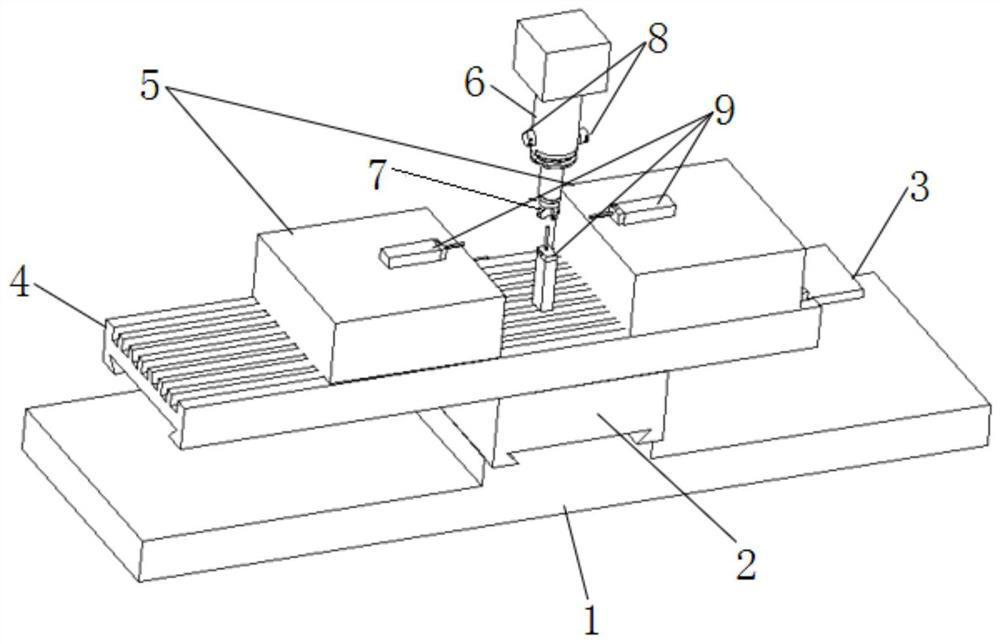
[0040] Such as figure 1 As shown, a machine tool tip point thermal error test layout structure of a machine tool thermal error modeling method includes a machine tool base 1, and an X guide rail 2 and a Y guide rail 3 are arranged on the machine tool base 1 shown in sequence. The Y guide rail 3 is provided with a magnetic base 4, and the magnetic base 4 is mounted with a workbench fixture 5, and the workbench fixture 5 is symmetrically arranged on the magnetic base 4, and one of the workbench fixtures 5 The middle part of the magnetic base 4 is provided with a displacement sensor 9, and the other two displacement sensors 9 are respectively symmetrically arranged on the workbench fixture 5;
[0041] Directly above the machine base 1 is provided with a main shaft 6, the lower end ...
Embodiment 3
[0045] This embodiment provides a thermal error testing arrangement structure at a certain point on the machine tool workbench of the method for modeling the thermal error of the whole machine tool in the first embodiment.
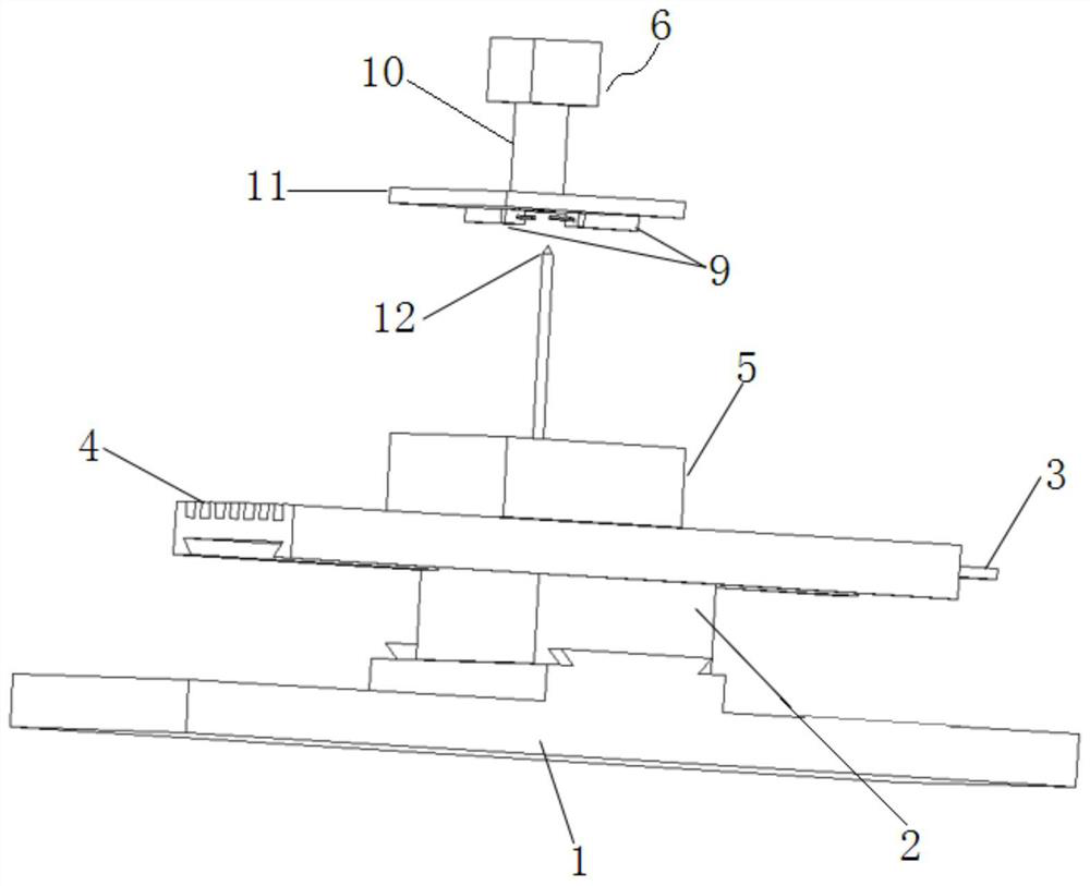
[0046] Such as figure 2 As shown, a thermal error test layout structure of a certain point of a machine tool workbench according to a thermal error modeling method of a machine tool includes a machine tool base 1, and an X guide rail 2 and a Y guide rail 3 are sequentially arranged on the machine tool base 1 shown , the Y guide rail 3 is provided with a magnetic base 4, the magnetic base 4 is mounted with a workbench fixture 5, and the workbench fixture 5 is located in the middle of the magnetic base 4 and holds a workpiece 12 above it. ;
[0047] A main shaft 6 is provided directly above the machine tool base 1, and a main shaft sleeve 10 is set on the main shaft 6, and a sleeve clamp 11 is installed under the main shaft sleeve 10, and a sleeve clamp 11...
PUM
 Abstract
Description
Claims
Application Information
 - R&D
- Intellectual Property
- Life Sciences
- Materials
- Tech Scout
- Unparalleled Data Quality
- Higher Quality Content
- 60% Fewer Hallucinations
Browse by: Latest US Patents, China's latest patents, Technical Efficacy Thesaurus, Application Domain, Technology Topic, Popular Technical Reports.
© 2025 PatSnap. All rights reserved.Legal|Privacy policy|Modern Slavery Act Transparency Statement|Sitemap|About US| Contact US: help@patsnap.com