Automatic rotor winding device for motor production

A technology of winding device and motor, applied in electromechanical devices, manufacturing of motor generators, motor components, etc., can solve the problems of inability to limit processing in time, messy copper wires, etc., and achieve the effect of improving equipment automation and work efficiency

Inactive Publication Date: 2020-09-15
东莞市奇趣机器人科技有限公司
View PDF0 Cites 3 Cited by
  • Summary
  • Abstract
  • Description
  • Claims
  • Application Information

AI Technical Summary

Problems solved by technology

[0003] The existing automatic winding device for the rotor cannot limit the position in time when winding the rotor, which leads to the disorder of the internal copper wires during winding. Therefore, we provide an automatic winding device for the rotor used in motor production. line device

Method used


Image

  • Automatic rotor winding device for motor production
  • Automatic rotor winding device for motor production
  • Automatic rotor winding device for motor production

Examples


Embodiment Construction

[0028] The following will clearly and completely describe the technical solutions in the embodiments of the present invention with reference to the accompanying drawings in the embodiments of the present invention. Obviously, the described embodiments are only some, not all, embodiments of the present invention.

[0029] In the description of the present invention, unless otherwise stated, the meaning of "plurality" is two or more; the terms "upper", "lower", "left", "right", "inner", "outer" , "front end", "rear end", "head", "tail", etc. indicate the orientation or positional relationship based on the orientation or positional relationship shown in the drawings, and are only for the convenience of describing the present invention and simplifying the description, rather than Indicates or implies that the device or element referred to must have a particular orientation, be constructed and operate in a particular orientation, and therefore should not be construed as limiting the...


PUM


Abstract

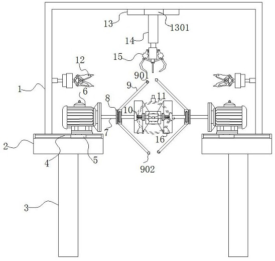
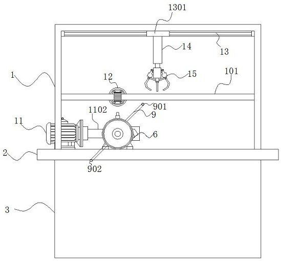
The invention discloses an automatic rotor winding device for motor production, and specifically relates to a rack. An objective table is arranged at the bottom of the rack. A hanging plate is mountedin the rack. An electric sliding rail is arranged in the objective table. The top of the sliding block is connected with a rotating motor. One side of the output shaft is connected with a conversionmodule. The end part of the output shaft is sleeved with a lead plate. A transposition device is arranged at the front end of the lead plate. A slide way is longitudinally arranged at the inner top ofthe rack. A lifting rod is arranged at the bottom of the sliding plate. According to the automatic rotor winding device for motor production, through a sliding structure formed by the sliding block and the electric sliding rail, the winding displacement hydraulic rod can drive the winding displacement device and the wire leading plate to slide left and right, the rotor can be conveniently clamped, winding can be conducted on the rotor, the winding displacement hydraulic rod stretches out and draws back to drive the blocking plate and the winding displacement plate to move left and right, copper wires can be evenly distributed on the rotor through sliding of the winding displacement plate, and therefore the copper wires can be regularly distributed on the rotor.

Description

technical field [0001] The invention relates to the technical field of motor production, in particular to an automatic winding device for rotors used in motor production. Background technique [0002] With the rapid development of high-end industrial product processing technology at home and abroad and the increasingly fierce market competition, controlling product quality has become the common pursuit of all enterprises, especially for motor processing. The requirements are getting higher and higher, especially the winding requirements inside the motor are becoming more and more stringent. [0003] The existing automatic winding device for the rotor cannot limit the position in time when winding the rotor, which leads to the disorder of the internal copper wires during winding. Therefore, we provide an automatic winding device for the rotor used in motor production. line device. Contents of the invention [0004] Aiming at the deficiencies of the prior art, the present ...

Claims


Application Information

Patent Timeline
IPC IPC(8): H02K15/09
CPCH02K15/09
Inventor 邓凯陈纯黄军梅曾宇凡
Owner 东莞市奇趣机器人科技有限公司
Why Eureka
Try Eureka