Resistance spot welding method for passivated coated steel plate

A coated steel plate and resistance spot welding technology, applied in resistance welding equipment, welding power supply, welding equipment, etc., can solve problems such as electrode steel plate adhesion, explosion points, and influence on welding quality, so as to reduce reaction, increase stability, and improve welding quality. The effect of spot weld quality

Active Publication Date: 2020-09-18
SHOUGANG CORPORATION
View PDF7 Cites 4 Cited by
  • Summary
  • Abstract
  • Description
  • Claims
  • Application Information

AI Technical Summary

Problems solved by technology

[0004] The invention provides a method for resistance spot welding of passivated coated steel plates to solve or partly solve the technical problems that electrodes are easily adhered to the steel plates, often cause explosive spots, and affect welding quality during resistance spot welding of passivated coated steel plates.

Method used


Image

  • Resistance spot welding method for passivated coated steel plate
  • Resistance spot welding method for passivated coated steel plate
  • Resistance spot welding method for passivated coated steel plate

Examples


Embodiment

[0063] (1) Preparation of welding plate group

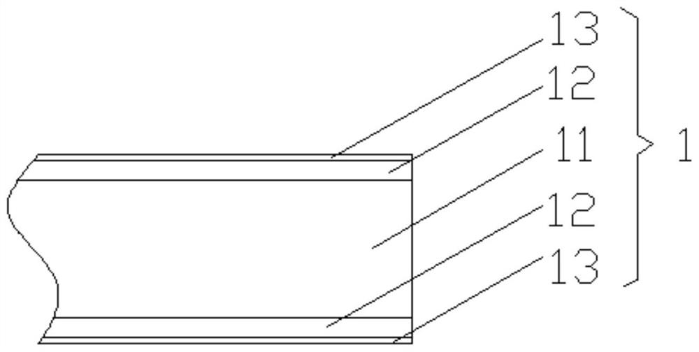
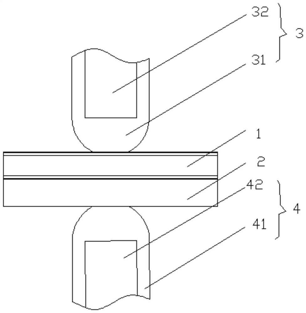
[0064] A passivated coated steel plate 1 and a test plate 2 are combined to form a welded plate group, and the passivated coated steel plate 1 is located on the top of the test plate 2, such as image 3 Shown; Wherein, passivation coating steel plate 1 thickness 1mm, substrate 11 is IF steel plate; Coating layer 12 is GI coating, thickness 7 μ m; Passivation layer 13 is chromium-free passivation layer, thickness 1 μ m; Test plate 2 is uncoated steel plate, Thickness 1 is mm; 3 pulses are to be used for continuous resistance welding;

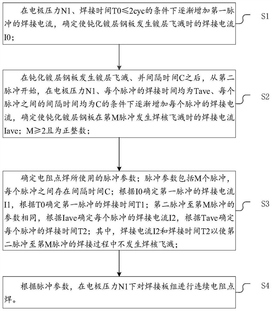
[0065] (2) Determine the pulse current I of the coating splash 0 and T 0

[0066] Put the welding test plate group used for the test between the upper electrode 3 and the lower electrode 4 for a pulse welding, the pressure between the electrodes N 1 Set to 3kN, welding time T 0 Determined to be 2cyc, gradually increase the welding current. When the welding current increases to 10000A, it is obser...


PUM

PropertyMeasurementUnit
thicknessaaaaaaaaaa
thicknessaaaaaaaaaa

Abstract

The invention discloses a resistance spot welding method for a passivated coated steel plate, and the method is applied to a welded plate group. The resistance spot welding method for the passivated coated steel plate comprises the following steps of determining the welding current I0 when coating splashing occurs on the passivated coated steel plate under the conditions of the electrode pressureof N1 and the welding time T0 less than or equal to 2 cyc; after a time interval C, from a second pulse, determining the welding current Iave when weld nugget splashing occurs on the passivated coatedsteel plate at the M-th pulse under the actions that the welding time of each pulse is Tave and the time interval between every two pulses is C; determining a pulse parameter used by resistance spotwelding, wherein the time interval between every two pulses is C; determining the welding current I1 of the first pulse according to I0; and determining the welding current I2 from the second pulse tothe M-th pulse according to the Iave, wherein the weld nugget splashing does not occur in a welding process from the second pulse to the M-th pulse. The method can reduce electrode adhesion, prolongthe service life of an electrode and improve the stability of the welding process.

Description

technical field [0001] The application relates to the technical field of resistance spot welding, in particular to a method for resistance spot welding of passivated coated steel plates. Background technique [0002] Resistance spot welding is a resistance welding method in which the weldment is assembled into a lap joint and pressed between the upper and lower columnar electrodes, and the base metal is melted by resistance heat to form a solder joint. Spot welding is mainly used for thin plate welding, and has a wide range of applications in industries such as automobiles and home appliances. [0003] With the increasing anti-corrosion performance of modern manufacturing industry, traditional coated steel sheets, such as galvanized steel sheets, galvanized iron alloy steel sheets, galvanized aluminum-magnesium steel sheets, etc., can no longer meet the needs of use due to white rust. The passivated coated steel plate prepared with a passivation film on the surface of the c...

Claims


Application Information

Patent Timeline
Patent Type & Authority Applications(China)
IPC IPC(8): B23K11/11B23K11/24B23K11/36
CPCB23K11/115B23K11/241B23K11/36
Inventor 张永强王鹏博付参鞠建斌伊日贵
Owner SHOUGANG CORPORATION
Why Eureka
Try Eureka