Ear line conveying device for mask production
A conveying device and ear wire technology, which is applied to conveyor objects, transportation and packaging, etc., can solve problems such as reducing the efficiency of masks and reducing the welding speed of ear wires, and achieve the effects of improving production quality, speed and production efficiency.
- Summary
- Abstract
- Description
- Claims
- Application Information
AI Technical Summary
Problems solved by technology
Method used
Image
Examples
Embodiment 1
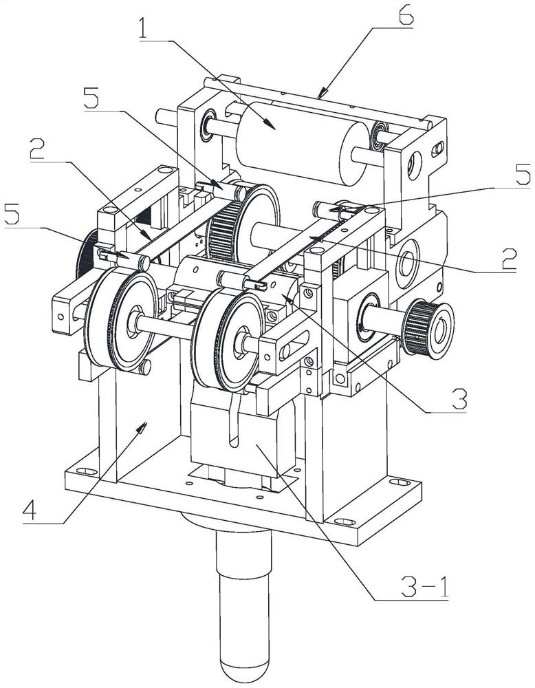
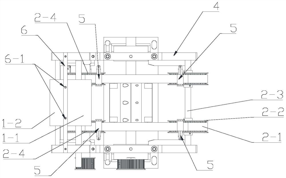
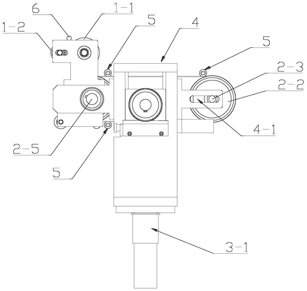
[0026] see Figure 1-Figure 10 The ear wire continuous welding equipment applying the ear wire conveying device of the present invention comprises a frame 4, a mask conveying device arranged on the frame 4, an ear wire conveying device and the mask strips transported by the mask conveying device for cutting and The welding device 3 that seals the edge and welds the ear wire delivered by the ear wire delivery device to the mask at the same time, wherein,
[0027] The welding device 3 includes a rotating shaft 3-2 arranged on the frame 4, a cutting module, a welding module and a first rotary drive mechanism for driving the rotating shaft 3-2 to rotate, wherein the cutting The module includes a cutting edge 3-4 arranged on the rotating shaft 3-2; the welding module includes an ultrasonic welding head 3-1 arranged on the frame 4 and an ultrasonic welding head arranged on the rotating shaft 3-2 3-1 above the pressing head 3-3, wherein the pressing head 3-3 is arranged on both side...
Embodiment 2
[0047] The difference between this embodiment and Embodiment 1 is that in this embodiment, a separate mask strip cutting station is set at the subsequent station of the ear wire welding station, which is used to cut off the mask strips that have welded the ear wire .
Embodiment 3
[0049] see Figure 11-Figure 15 ,in, Figure 15 The middle mark 12 is the ear wire, and the mark 13 is the mask strip;
[0050] The difference between this embodiment and embodiment 1 is:
[0051] see Figure 11-Figure 15 , the ear wire conveying drive mechanism includes a runner 8 arranged on the rotating shaft 3-2, and the plurality of clamping mechanisms 5 are installed on the runner 8; The groove 8-1 for matching the ear wire, the groove 8-1 extends along the circumferential direction of the runner 8; the pressing head 3-3 is installed on the outer peripheral surface of the runner 8, And it is located at the rear of the clamping mechanism 5 along the rotation direction of the runner 8, so that the groove 8-1 is faulted at the position of the pressing head 3-3; 1-1 and the second conveying roller 1-2 wrap around the guide groove 7-3 of the corresponding guide wheel 7-1 in the guide wheel set 7 after coming out.
[0052] The thread clamping mechanism 5 and the pressing ...
PUM
 Abstract
Description
Claims
Application Information
 - R&D
- Intellectual Property
- Life Sciences
- Materials
- Tech Scout
- Unparalleled Data Quality
- Higher Quality Content
- 60% Fewer Hallucinations
Browse by: Latest US Patents, China's latest patents, Technical Efficacy Thesaurus, Application Domain, Technology Topic, Popular Technical Reports.
© 2025 PatSnap. All rights reserved.Legal|Privacy policy|Modern Slavery Act Transparency Statement|Sitemap|About US| Contact US: help@patsnap.com


