
A cable laying device for electric power engineering construction and its application method

A technology of electric power engineering and cables, which is applied in the directions of cable laying equipment, transportation and packaging, and thin material handling, etc. It can solve problems such as the need for a period of transition time, the easy increase of belt loss, and the reduction of belt tension, so that the direction of transmission can be achieved. Controlling, reducing failures, not easy to be scattered and uneven

Active Publication Date: 2021-12-14
广州恒泰电力工程有限公司
View PDF11 Cites 0 Cited by
  • Summary
  • Abstract
  • Description
  • Claims
  • Application Information

AI Technical Summary

Problems solved by technology

In the process of cable laying, the traction force is often controlled according to the experience of the operators of the construction unit, and it takes a transitional time to adjust the traction force to an appropriate size.
When the traction force is not well controlled, the belt loss of the tractor is likely to increase, and the belt is prone to slack, resulting in a decrease in the tension of the belt. reduce construction efficiency
[0005] The above-mentioned existing technical solutions have the following defects: when cables are laid in the pipeline, due to improper traction control, the belt is prone to slack, which in turn leads to deviation of the belt, causing faults, affecting the laying of cables, and making the construction efficiency reduce

Method used


Image

  • A cable laying device for electric power engineering construction and its application method
  • A cable laying device for electric power engineering construction and its application method
  • A cable laying device for electric power engineering construction and its application method

Examples


Embodiment 1

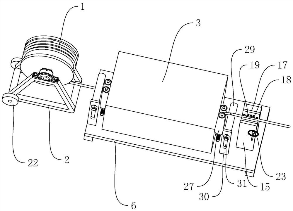
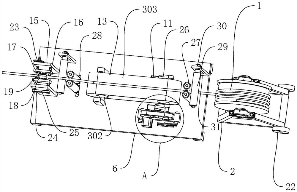
[0047] refer to figure 1 Embodiment 1 of the present invention provides a cable laying device for electric power engineering construction, including a wire frame 2 and a tractor 3, the cable 1 is wound on the wire frame 2 and laid along the length direction of the pipeline through the tractor 3 The bottom of the wire frame 2 is rotatably connected with a pulley 22 at one end, and there are two pulleys 22 arranged along a straight line. The bottom of the tractor 3 is fixed with a mounting base 6 .

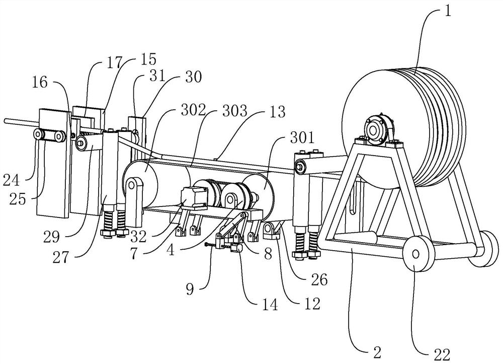
[0048] refer to figure 2 with Figure 5 The tractor 3 includes a driving wheel 301 and a driven wheel 302 which are rotatably arranged, and the driven wheel 302 is fixed on the upper surface of the mounting base 6, and the upper surface of the mounting base 6 is respectively provided with horizontally arranged chutes towards the two ends of the driven wheel 302 11, slide block 12 is all slidably connected in the chute 11 (see image 3 ), the two ends of the driving wheel 301 are...

Embodiment 2

[0064] Embodiment 2 of the present invention provides a method for using a cable laying device for power engineering construction, including a tension sensor 13 that monitors the tension of the belt 303 in real time, and reports to the microcontroller when the tension of the belt 303 is less than a preset value. Send a trigger signal;

[0065] The microcontroller receives the electrical signal of the tension sensor 13 and sends the starting electrical signal to the motor 14;

[0066] The motor 14 rotates and drives the screw rod 9 to rotate. The screw rod 9 drives the adjustment rod 8 to slide along the length direction of the screw rod 9. The adjustment rod 8 drives the retracting rod 7 hinged therewith to rotate, drives the adjustment seat 5 to move, and the adjustment seat 5 drives the gear 4 to move. 4 drive the driving wheel 301 to move, and change the distance between the driving wheel 301 and the driven wheel 302;

[0067] Until the tension value of the belt 303 is equ...


PUM


Abstract

The present invention aims to provide a cable laying device for electric power engineering construction and its use method, which includes a wire stand and a tractor, the tractor includes a driving wheel and a driven wheel, and a belt is wound between the driving wheel and the driven wheel , the axial direction of the driving wheel is fixed with a gear, the bottom of the gear is fixed with an adjustment seat, and the bottom of the adjustment seat is provided with a mounting seat. There are at least four retracting rods hinged between the adjusting seat and the mounting seat, and one of the retracting rods is hinged. An adjustment rod is provided, and a horizontally arranged screw is connected to the mounting seat. The end of the adjustment rod away from the pull rod is threadedly connected to the screw. The end of the screw is fixedly installed with a driving mechanism that automatically drives the screw to rotate. seat. It solves the problem that the belt is prone to slack due to improper traction control when laying cables in the pipeline. The invention has the effects of automatically adjusting the belt when the belt is slack, reducing the deviation of the belt and causing failures, and improving the construction efficiency.

Description

technical field [0001] The invention relates to the technical field of electric power engineering construction, in particular to a cable laying device for electric power engineering construction and a use method thereof. Background technique [0002] At present, when laying cables outdoors, the pipelines are generally buried first, and then the cables are pulled and laid along the length of the pipelines by a tractor, so as to realize the cable laying in the pipelines. [0003] The traction machine is mainly composed of an engine, a gearbox and a transmission device, wherein the transmission device realizes the forward transmission of the cable through a belt. [0004] In particular, during the cable laying process, controlling the traction force on the cable is the key to ensuring the laying quality. In the cable laying process, the traction force is often controlled according to the experience of the operators of the construction unit, and it takes a transitional time to ...

Claims


Application Information

Patent Timeline
Patent Type & Authority Patents(China)
IPC IPC(8): B65H51/14B65G23/44B65H57/14B65H57/04H02G1/06
CPCB65H51/14B65G23/44B65H57/14B65H57/04H02G1/06B65H2701/34
Inventor 钟敬城于海艳朱瑞宾刘建波林坤盛陈残雪陈飞鹏
Owner 广州恒泰电力工程有限公司
Learn More