Steel reinforcement cage continuous manufacturing equipment and steel reinforcement cage manufacturing method

A technology for steel cages and equipment, which is applied to excavation, structural elements, building components, etc., can solve the problems of difficulty in construction coordination and communication of construction enterprises, difficult to control assembly and assembly accuracy, and reduced operation efficiency, so as to improve the efficiency of on-site assembly and avoid The effect of decentralization is difficult and the processing cost is reduced

Active Publication Date: 2020-09-18
CHINA RAILWAY ENGINEERING EQUIPMENT GROUP CO LTD
View PDF9 Cites 0 Cited by
  • Summary
  • Abstract
  • Description
  • Claims
  • Application Information

AI Technical Summary

Problems solved by technology

[0002] During the building construction process, most of the underground enclosure structures adopt the structural form of piles or diaphragm walls. In order to improve the strength of the support bodies of piles and diaphragm walls, it is necessary to place steel cages in them; The length of the internal reinforcement cage is also increasing; conventionally, the reinforcement cage is lowered in sections and segments, which will bring about technical problems such as increased construction costs, reduced operating efficiency, and difficulty in controlling assembly and assembly accuracy, especially When there are bridges, cables, railways and other public facilities in the construction area, in order to cooperate with the layout and installation of the reinforcement cage of the construction enclosure structure, it is usually necessary to adopt the cooperation method of power outage and outage, which brings a lot of inconvenience to the surrounding area of ​​the construction environment and brings great inconvenience to the construction enterprises. It is very difficult to coordinate and communicate the construction, so it is very necessary to provide a continuous production equipment for steel cages and a production method for steel cages.

Method used


Image

  • Steel reinforcement cage continuous manufacturing equipment and steel reinforcement cage manufacturing method
  • Steel reinforcement cage continuous manufacturing equipment and steel reinforcement cage manufacturing method
  • Steel reinforcement cage continuous manufacturing equipment and steel reinforcement cage manufacturing method

Examples


Embodiment Construction

[0035] Specific embodiments of the present invention will be described in detail below in conjunction with the accompanying drawings.

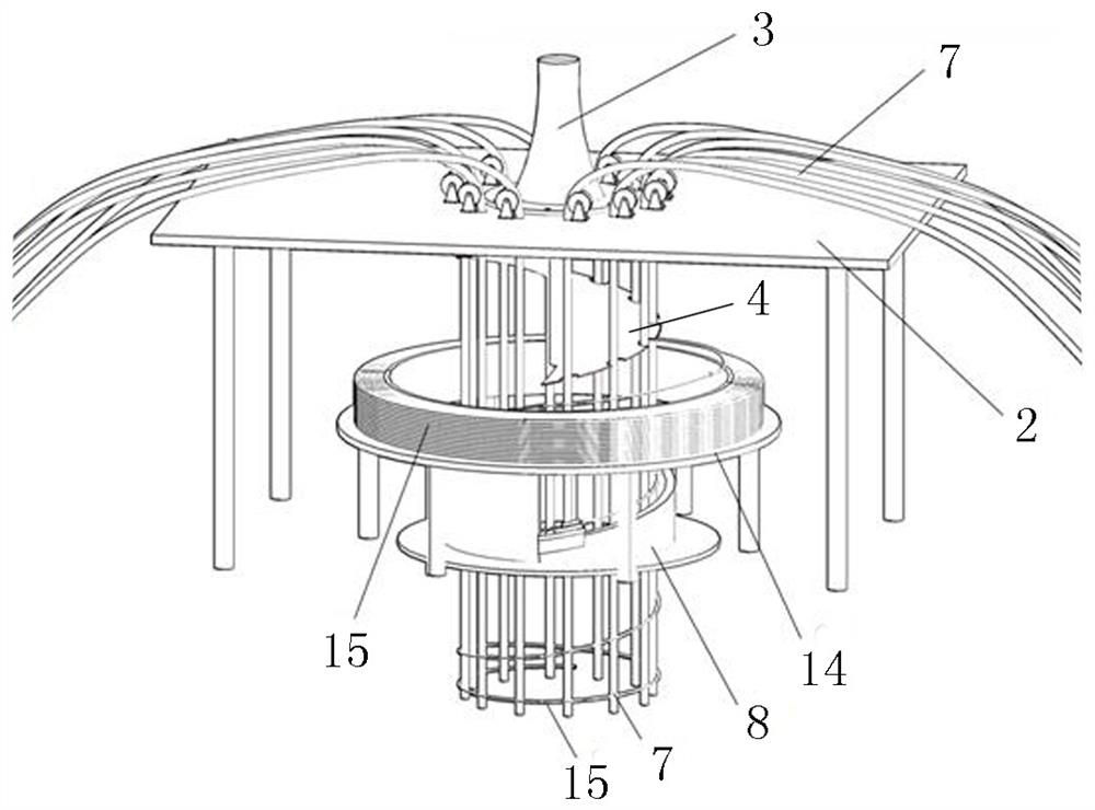
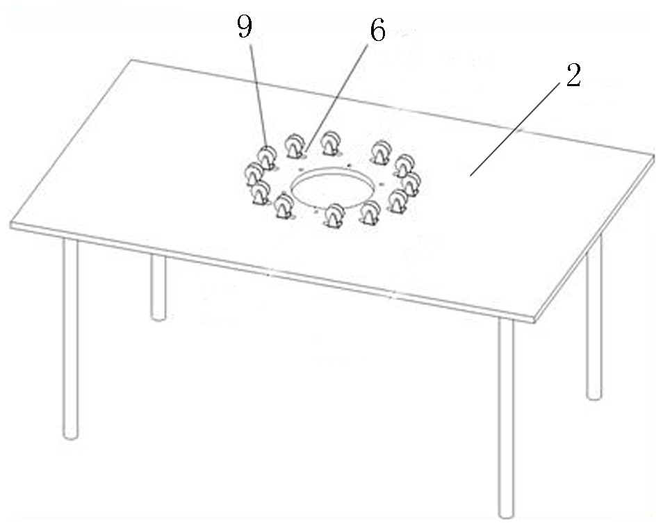
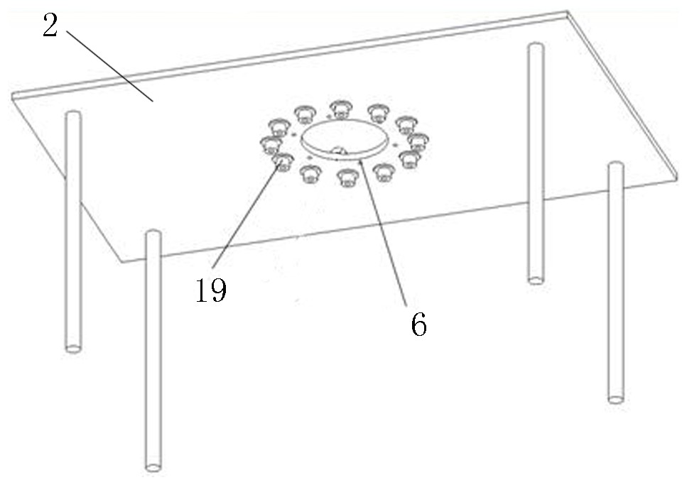
[0036] Such as Figure 1-8As shown, a kind of steel cage continuous production equipment is provided, including a forming enclosure structure slot 1, a reinforcement cage platform 2 is arranged above the forming enclosure structure slot, and a lowering cage is installed above the reinforcement cage platform. The propulsion device 3 is used for the lowering power source output of the steel cage; the front end of the lowering propulsion device is connected with a bearing plate 4, and a plurality of grooves 5 are evenly distributed on the bearing plate, and the number of grooves is the same as that of the steel cage The number of main bars is consistent; on the table of the steel cage stand, there are also a plurality of piercing holes 6 evenly distributed, and the main bars 7 of the steel cage are penetrated in the piercing holes, and the number...


PUM


Abstract

The invention belongs to the technical field of building construction, and particularly relates to steel reinforcement cage continuous manufacturing equipment and a steel reinforcement cage manufacturing method. The equipment comprises a shaping enclosure structure slot hole, a steel reinforcement cage rack is arranged above the shaping enclosure structure slot hole, and a lowering pushing deviceis installed above the steel reinforcement cage rack; a bearing pressing plate is connected to the front end of the lowering pushing device, a plurality of grooves are uniformly distributed in the bearing pressing plate, and a plurality of reinforcement threading holes are uniformly distributed in the rack surface of the steel reinforcement cage rack; and a main reinforcement of the steel reinforcement cage is inserted into each reinforcement threading hole, and a stirrup device is fixedly arranged at the lower end of the steel reinforcement cage rack. According to the steel reinforcement cagecontinuous manufacturing equipment and the steel reinforcement cage manufacturing method, on-site continuous manufacturing and lowering functions of the steel reinforcement cage can be effectively realized, continuous output of the main reinforcements of the steel reinforcement cage is guaranteed, transition joint connection is not needed in the middle, the field processing operation efficiency,processing quality and installation precision of the steel reinforcement cage are improved, and the steel reinforcement cage continuous manufacturing equipment is suitable for large-scale popularization and application.

Description

technical field [0001] The invention belongs to the technical field of building construction; in particular, it relates to a continuous manufacturing equipment for steel cages and a manufacturing method for steel cages. Background technique [0002] During the building construction process, most of the underground enclosure structures adopt the structural form of piles or diaphragm walls. In order to improve the strength of the support bodies of piles and diaphragm walls, it is necessary to place steel cages in them; The length of the internal reinforcement cage is also increasing; conventionally, the reinforcement cage is lowered in sections and segments, which will bring about technical problems such as increased construction costs, reduced operating efficiency, and difficulty in controlling assembly and assembly accuracy, especially When there are bridges, cables, railways and other public facilities in the construction area, in order to cooperate with the layout and inst...

Claims


Application Information

Patent Timeline
Patent Type & Authority Applications(China)
IPC IPC(8): E02D17/04E04C5/06E04G21/12
CPCE02D17/04E04C5/06E04G21/12
Inventor 白中坤毕程程李洋
Owner CHINA RAILWAY ENGINEERING EQUIPMENT GROUP CO LTD
Why Eureka
Try Eureka