
Magnetic field sensing device based on magnetofluid

A sensing device and magnetic fluid technology, which is applied in the direction of magnetic field measurement, magnetic field size/direction, etc. using magneto-optical equipment, can solve problems such as electromagnetic interference, metal cable interference, and high equipment manufacturing costs, and achieve good electromagnetic insulation , fast response and simple structure

Active Publication Date: 2020-09-18
SHANTOU UNIV
View PDF19 Cites 0 Cited by
  • Summary
  • Abstract
  • Description
  • Claims
  • Application Information

AI Technical Summary

Problems solved by technology

The magnetic field measurement is inseparable from the magnetic field sensor. In order to ensure the accuracy of the magnetic field strength measurement, the magnetic field sensor is usually required to minimize the disturbance of the measured magnetic field. However, the traditional magnetic field sensor usually uses an active metal probe, which will disturb the measured electromagnetic field. distribution; and, the metal cables that carry the signal for measuring the magnetic field are subject to interference from electromagnetic noise
[0003] In summary, the existing magnetic field sensing methods are subject to many limitations due to problems such as low measurement accuracy, high equipment manufacturing costs, and electromagnetic interference, and it is difficult to apply them on a large scale.

Method used


Image

  • Magnetic field sensing device based on magnetofluid
  • Magnetic field sensing device based on magnetofluid
  • Magnetic field sensing device based on magnetofluid

Examples


Embodiment Construction

[0021] The idea, specific structure and technical effects of the present invention will be clearly and completely described below in conjunction with the embodiments and accompanying drawings, so as to fully understand the purpose, scheme and effect of the present invention. It should be noted that, in the case of no conflict, the embodiments in the present application and the features in the embodiments can be combined with each other.

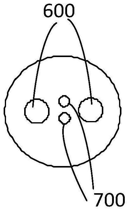
[0022] refer to figure 1 ,like figure 1 Shown is a magnetic field sensing device based on magnetic fluid provided by the embodiment, including:

[0023] Broadband light source 100, polarizer 200, polarization controller 300, sensing unit 400, and spectrometer 500, the broadband light source 100, polarizer 200, polarization controller 300, sensing unit 400, and spectrometer 500 pass through a single-mode optical fiber in sequence connection, the sensing unit 400 is a polarization-maintaining optical fiber with a single-mode optical fiber wel...


PUM

PropertyMeasurementUnit
Core diameteraaaaaaaaaa
Cladding diameteraaaaaaaaaa
Pore diameteraaaaaaaaaa

Abstract

The invention relates to the technical field of optical fiber sensing, particularly relates to a magnetic field sensing device based on magnetic fluid. The device comprises a broadband light source, apolarizer, a polarization controller, a sensing unit and a spectrograph, the broadband light source, the polarizer, the polarization controller, the sensing unit and the spectrograph are connected insequence through single-mode optical fibers, the sensing unit is a polarization maintaining optical fiber, the two ends of the polarization maintaining optical fiber are connected with the single-mode optical fibers in a welded mode respectively, and air holes of the polarization maintaining optical fiber are filled with magnetofluid; the polarization controller is configured to enable linearly polarized light to enter the polarization maintaining optical fiber in a direction forming an angle of 45 degrees with a fast axis of the polarization maintaining optical fiber; the linearly polarizedlight is formed after light output by the broadband light source passes through the polarizer, the spectrograph is used for recording a spectrogram, and the magnetic field sensing device has the advantages of being high in sensitivity, good in electromagnetic insulativity, high in response speed, simple in structure and lower in cost.

Description

technical field [0001] The invention relates to the technical field of optical fiber sensing, in particular to a magnetic field sensing device based on magnetic fluid. Background technique [0002] Magnetic field measurement is of great significance in many fields of scientific research and engineering technology, especially in the fields of power system, electromagnetic compatibility and microwave technology. The magnetic field measurement is inseparable from the magnetic field sensor. In order to ensure the accuracy of the magnetic field strength measurement, the magnetic field sensor is usually required to minimize the disturbance of the measured magnetic field. However, the traditional magnetic field sensor usually uses an active metal probe, which will disturb the measured electromagnetic field. distribution; and, the metal cables that carry the signal for measuring the magnetic field are disturbed by electromagnetic noise. [0003] In summary, the existing magnetic fi...

Claims


Application Information

Patent Timeline
IPC IPC(8): G01R33/032
CPCG01R33/032
Inventor 陈晓涌阮家剑马朋雷曲航
Owner SHANTOU UNIV
Learn More