Lower chamber structure of reactor container and reactor container

A reactor vessel and reactor technology, applied in the field of nuclear reactors, can solve problems such as uneven distribution and liquid fuel flow differences, and achieve the effects of accurately matching the core power distribution, avoiding vortices, and having no obvious vortices.

Active Publication Date: 2020-09-18
SHANGHAI INST OF APPLIED PHYSICS - CHINESE ACAD OF SCI
View PDF11 Cites 1 Cited by
  • Summary
  • Abstract
  • Description
  • Claims
  • Application Information

AI Technical Summary

Problems solved by technology

[0005] The technical problem to be solved by the present invention is to overcome the fluid in the lower chamber of the reactor structure whose inlet is located at the bottom of the reactor in the prior art to generate a large number of vortices, and make the difference between entering the core The liquid fuel flow rate of the channel varies greatly and the defects of uneven distribution provide a lower chamber structure of the reactor vessel and a reactor vessel

Method used


Image

  • Lower chamber structure of reactor container and reactor container
  • Lower chamber structure of reactor container and reactor container
  • Lower chamber structure of reactor container and reactor container

Examples


Embodiment 1

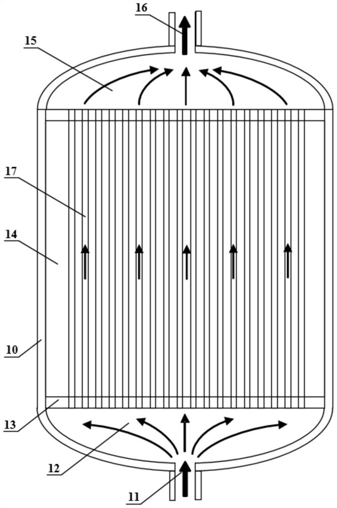
[0060] figure 1 It is a liquid fuel molten salt reactor vessel 10, which includes a reactor lower chamber inlet 11, a reactor lower chamber 12, a core support base plate 13, a reactor core structural member 14, a reactor upper chamber 15, a reactor outlet 16, and a core channel 17.

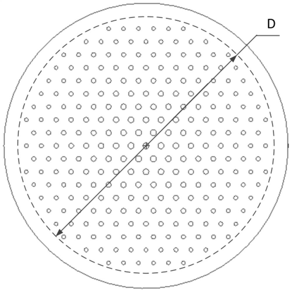
[0061] figure 2 The middle core support bottom plate 13 is fixedly welded on the support member of the inner wall of the reactor vessel 10, and there are perforations corresponding to the positions of the core liquid fuel channels. The size of the perforations can be adjusted in different regions according to the flow distribution requirements. Arranged radially from the center to the periphery, the channels on the same circle have the same size, and the channels on different circles have different sizes (such as figure 2 shown). It is assumed that the diameter of the circular area where holes are distributed on the core support base plate 13 (ie, the circular area where the core channels are...

Embodiment 2

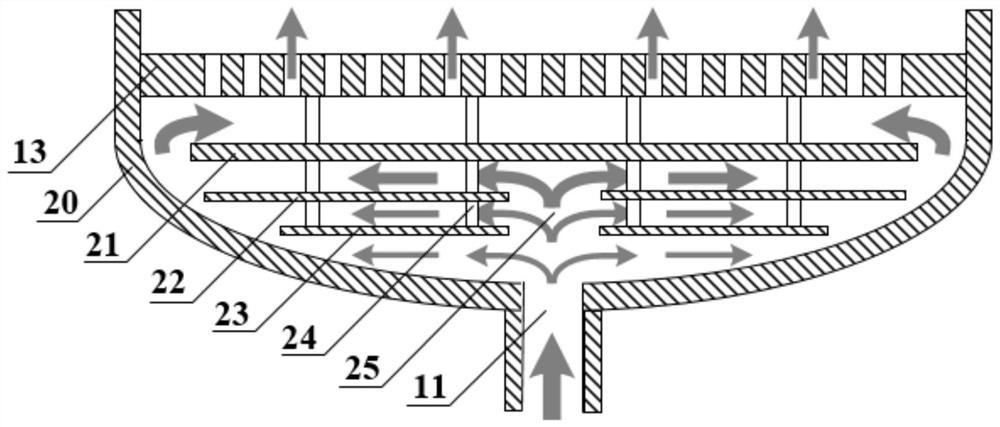
[0066] The structure of the lower chamber in this embodiment is the same as that in Embodiment 1. Assume that the diameter of the circle corresponding to the overall distribution area of ​​the channels on the core support base plate 13 is 1.7m, and the diameter of the core support plate is 1.9m (due to the existence of the core reflection layer, the diameter of the flow channel coverage area of ​​the molten salt reactor core is generally smaller than that of the entire core. diameter, such as image 3 As shown), the reactor lower chamber 12 is a semi-ellipsoid structure, and the diameter of the reactor lower chamber inlet 11 is 0.15m.

[0067] The thickness of the flow distribution plate circular plate 21 is 0.02m, the diameter is 1.7m, and the vertical distance between the upper surface of the flow distribution plate circular plate 21 and the lower surface of the core support bottom plate 13 is 0.08m. The vertical distance between the lower surface of the flow distribution p...


PUM


Abstract

The invention discloses a lower chamber structure of a reactor container and the reactor container. The lower chamber structure comprises a reactor core supporting bottom plate, a reactor container lower sealing head and a reactor lower chamber inlet, a flow distribution plate circular plate is fixedly connected with a reactor core supporting bottom plate in parallel, the radial width of the flowdistribution plate circular plate is smaller than that of the reactor core supporting bottom plate, the radial width of the flow distribution plate circular plate is greater than or equal to the diameter of the circular area with the holes in the reactor core supporting bottom plate and is not in contact with the interior of the reactor container lower sealing head an inlet of the reactor lower chamber is formed in the reactor container lower seal head in the area below the flow distribution plate circular plate, the device further comprises a perforated circular plate on the flow distribution plate, and through holes are formed in the perforated circular plate on the flow distribution plate. According to the lower cavity structure, the flow field characteristic of the lower cavity is effectively improved, vortexes in the lower cavity are avoided, flow distribution is conducted on fluid in combination with the reactor core lower supporting plate, and the flow distribution of the fluidentering the reactor core reaches the design target of the reactor.

Description

technical field [0001] The invention relates to the field of nuclear reactors, in particular to a lower chamber structure of a reactor vessel and the reactor vessel. Background technique [0002] The liquid fuel molten salt nuclear reactor body is composed of a pressure vessel, graphite components and metal components in the reactor. The reactor inlet is located at the bottom of the lower head of the pressure vessel, and the outlet is located at the top of the upper head of the pressure vessel; the fuel salt melts in the carrier salt and follows the carrier salt Flow, the fuel salt and carrier salt fluid enter the lower chamber of the reactor from the bottom of the reactor vessel, enter the core through the lower support plate of the core, release the fission energy in the core flow channel composed of graphite, enter the upper chamber, and then flow from the The top outlet of the upper chamber flows out, thereby realizing heat transfer (such as figure 1 shown). [0003] D...

Claims


Application Information

Patent Timeline
Patent Type & Authority Applications(China)
IPC IPC(8): G21C13/024G21C13/02G21C3/54
CPCG21C13/024G21C13/02G21C3/54Y02E30/30
Inventor 田健王允张金红周翀傅瑶邹杨
Owner SHANGHAI INST OF APPLIED PHYSICS - CHINESE ACAD OF SCI
Why Eureka
Try Eureka