
Thermal history control method for thermal printing head, thermal printer and computer-readable storage medium

A technology of a thermal print head and a control method, applied to thermal printers and computer-readable storage media, in the field of thermal history control of thermal print heads, and can solve problems such as affecting printing quality, insufficient color density of font patterns, smearing, etc. problems, to achieve the effect of clear fonts or images, smooth heating, and avoid smearing

Active Publication Date: 2020-09-22
珠海柏印自动化设备有限公司
View PDF5 Cites 5 Cited by
  • Summary
  • Abstract
  • Description
  • Claims
  • Application Information

AI Technical Summary

Problems solved by technology

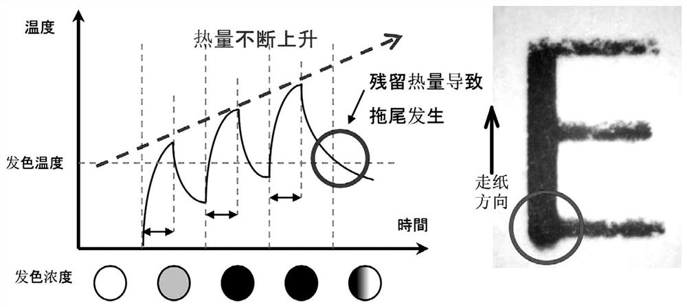
[0005] refer to figure 1 , due to the principle of the heating element being energized and heated, heat accumulation and dissipation will inevitably occur, and there is a certain delay in heating and heat dissipation. In high-speed printing, it is easy to cause insufficient color density or smearing of font patterns. Now, Seriously affect the print quality

Method used

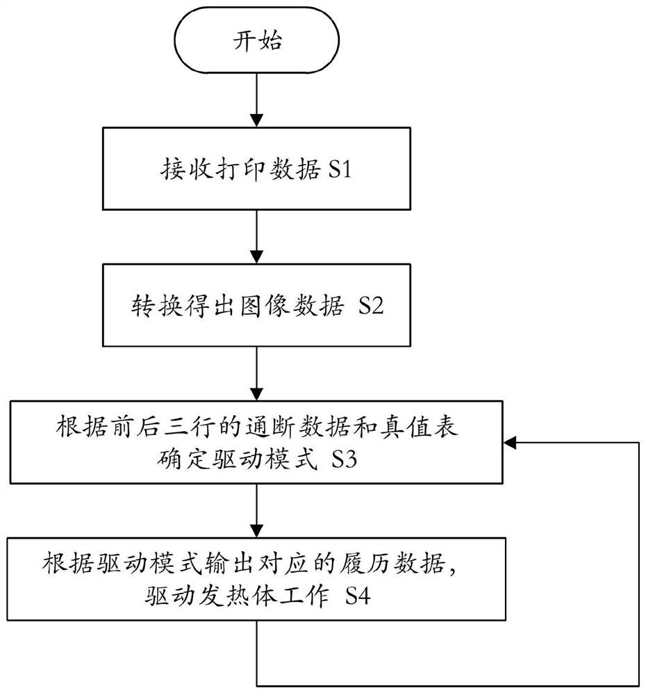

Image

  • Thermal history control method for thermal printing head, thermal printer and computer-readable storage medium
  • Thermal history control method for thermal printing head, thermal printer and computer-readable storage medium
  • Thermal history control method for thermal printing head, thermal printer and computer-readable storage medium

Examples


Embodiment Construction

[0036] Embodiment of thermal history control method of thermal print head:

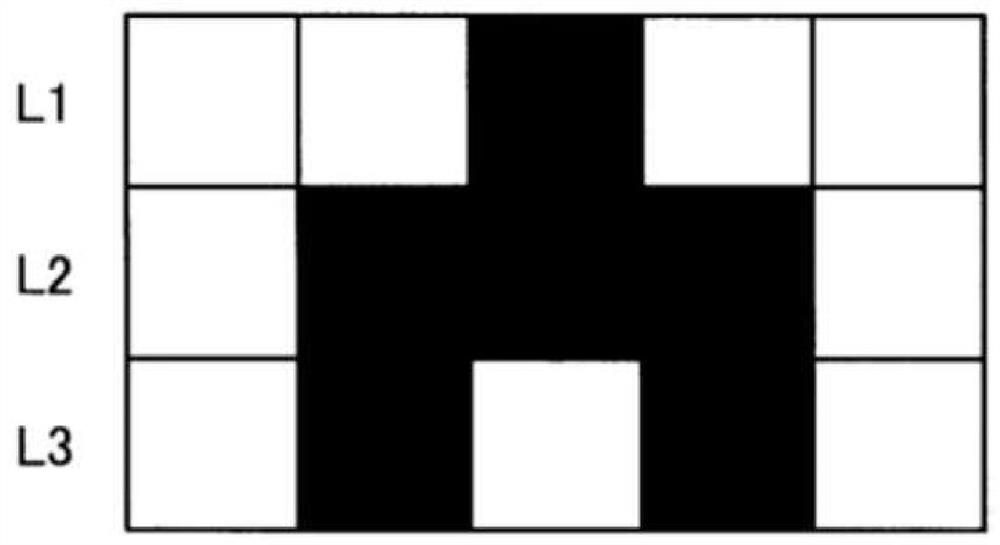
[0037] refer to figure 2 , the thermal printhead includes a thermal printhead, a processor and a memory, the processor is electrically connected to the thermal printhead, and when the processor executes the thermal history control method, it first executes step S1 to receive the print output from the computer, terminal or server data, and then execute step S2 to convert the image data according to the print data, refer to image 3 , image 3 It is a schematic diagram of image data. The image data is a dot matrix image converted from printing data, and then digitally processed to form image data. Each row of white pixels from L1 to L3 corresponds to the power-on cut-off (OFF) of the heating element, which is represented by "0" Indicates the state of energization and cut-off, and the black pixels in each row of L1 to L3 correspond to the heating element energization and conduction (ON). When "1" is u...


PUM


Abstract

The invention provides a thermal history control method for a thermal printing head, a thermal printer and a computer-readable storage medium. The thermal history control method comprises the steps ofreceiving printing data, obtaining image data according to the printing data, obtaining on-off data of a current printing row, a previous printing row and a next printing row of a heating body of thethermal printing head from the image data, determining a driving mode of the heating body according to the on-off data and a truth-value table, and outputting the history data corresponding to the driving mode to the thermal printing head to drive the heating body to operate. By predicting and judging the accumulated heat of a heating element of the printing head in advance and setting and inquiring the truth-value table, the heating time of the heating body can be effectively controlled, so that the printing quality is improved by smooth heating and smooth heat dissipation, a printed font orimage is clearer, and trailing smear is avoided.

Description

technical field [0001] The invention relates to the field of thermal printing, in particular to a thermal history control method of a thermal print head, a thermal printer and a computer-readable storage medium. Background technique [0002] With the popularization and application of thermal printers in all walks of life, thermal printing structures are not only used in bank ATMs, cash register terminals, takeaway terminals, catering terminals and e-commerce delivery terminals, especially for catering and e-commerce , Printing in the express delivery industry is growing rapidly, which puts forward higher requirements for the stability and durability of printers. [0003] The core printing component in a thermal printer is the thermal print head, which is the main execution unit for printing images on thermal printers such as bills or barcodes. The thermal print head is composed of a row of heating elements. Relatively dense, ranging from 200dpi to 600dpi, these heating elem...

Claims


Application Information

Patent Timeline
Patent Type & Authority Applications(China)
IPC IPC(8): B41J2/355B41J2/32G06T9/00
CPCB41J2/32B41J2/3556G06T9/00
Inventor 郑小春梁乾乐
Owner 珠海柏印自动化设备有限公司
Learn More