
Threshold structure of electric vehicle

An electric vehicle, threshold technology

Active Publication Date: 2020-09-22
ZHEJIANG LEAPMOTOR TECH CO LTD
View PDF10 Cites 0 Cited by
  • Summary
  • Abstract
  • Description
  • Claims
  • Application Information

AI Technical Summary

Problems solved by technology

However, this structure has several disadvantages. First, in electric vehicles with rear motors, connecting pipelines such as cooling pipelines and charging harnesses need to be installed between the vehicle control system at the front of the vehicle and the driving motor at the rear of the vehicle. These pipelines will It inevitably occupies the installation space of the battery pack. Second, when the electric vehicle is hit by a side column, the threshold beam becomes the only barrier structure to protect the battery pack and connecting pipelines.

Method used


Image

  • Threshold structure of electric vehicle
  • Threshold structure of electric vehicle
  • Threshold structure of electric vehicle

Examples


Embodiment 1

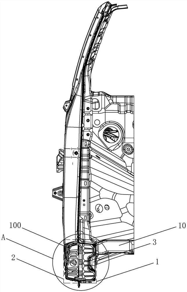
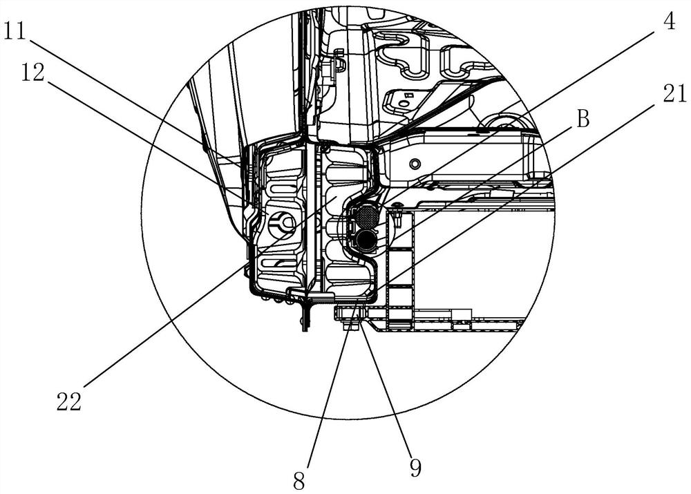
[0025] like figure 1 , 2 As shown, a threshold structure of an electric vehicle includes threshold components 100 arranged on both sides of the battery pack of the electric vehicle. The outer sill assembly 2 on the outside of the inner sill assembly is provided with an integrated wire harness accommodation chamber 3 between the sill assembly and the battery pack, and the integrated wire harness accommodation chamber is arranged inside the inner sill assembly. Compared with the traditional sill beam structure, the sill assembly of the combined structure has a richer combination scheme. Through the cooperation of the inner sill assembly and the outer sill assembly, the side impact force transmission and collapse energy absorption that a single sill beam does not have can be realized. Function, when the outer door sill assembly is damaged but the inner door sill assembly is not damaged, only the outer door sill assembly needs to be repaired and replaced, which improves the mater...

Embodiment 2

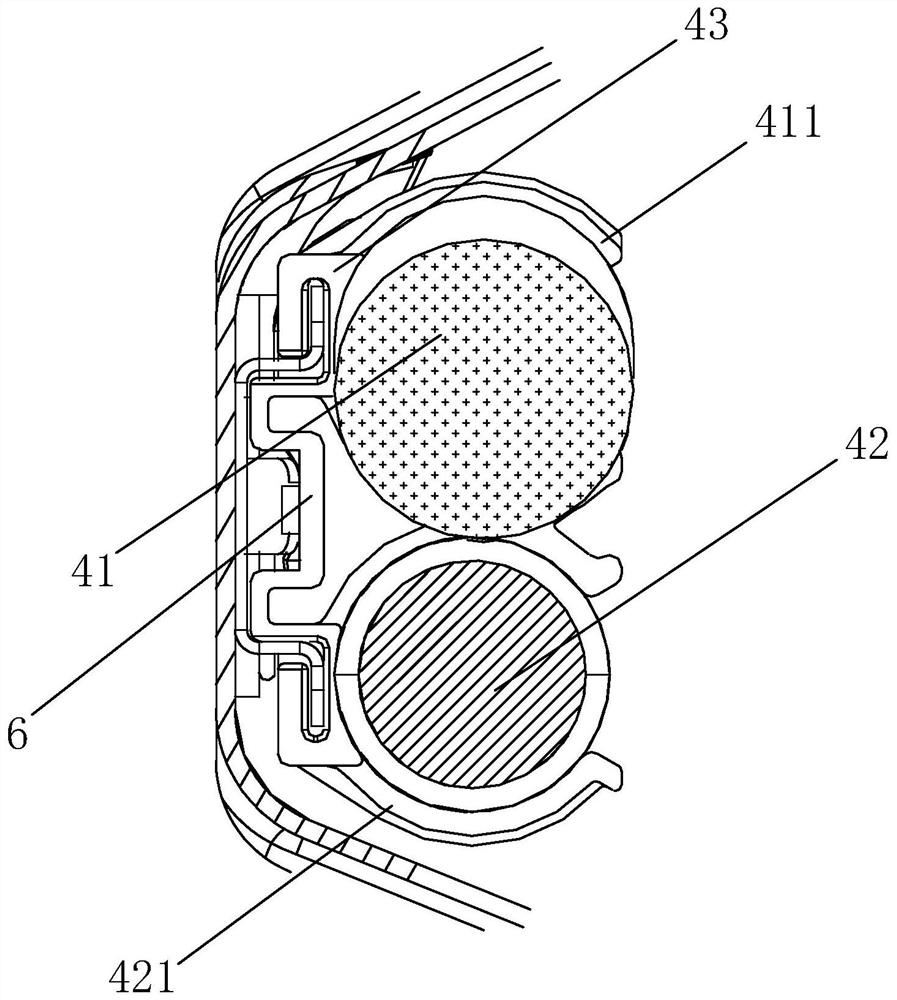
[0032] The difference from Embodiment 1 is that the protective layer in this embodiment does not use a sleeve made of hard material, but adopts a surrounding airbag component, and the protective layer includes a number of micro airbags 7 evenly arranged around it. like Figure 4 As shown, the surrounding airbag assembly plays a certain buffering role when the door sill assembly is subjected to side impact force, and the 360° buffer protection of the pipeline group is realized through the micro airbag arranged around the pipeline group.

[0033] A safety chamber 71 is provided on the side of the micro-airbag away from the pipeline group, and a wall breaking member 72 is provided in the safety chamber. The safety cavity is an open structure. When the micro-airbag is subjected to external pressure, it is determined according to the pressure whether the broken wall part installed on the inside touches the top of the safe cavity. When the external force is so large that the broken...


PUM


Abstract

The invention discloses a threshold structure of an electric vehicle. The threshold structure includes a threshold assembly arranged on two sides of a battery pack of the electric vehicle, wherein thethreshold assembly is a combined structural part and comprises an inner threshold assembly arranged on the outer side of the battery pack and an outer threshold assembly arranged on the outer side ofthe inner threshold assembly, an integrated wiring harness accommodating cavity is formed between the threshold assembly and the battery pack, and the integrated wiring harness accommodating cavity is formed on the inner side of the inner threshold assembly in a penetrating mode. A traditional threshold beam is optimized into the threshold assembly, and the energy absorption and side impact forceconduction functions of the threshold assembly are added; the integrated wire harness accommodating cavity is arranged between the threshold assembly and the battery pack, so that the arrangement relationship between the threshold assembly and a connecting pipeline is optimized, and a solution is provided for maximizing the mounting space of the battery pack.

Description

technical field [0001] The invention relates to the technical field of electric vehicle manufacturing, in particular to a threshold structure of an electric vehicle. Background technique [0002] As a new energy vehicle, electric vehicle has become more and more research hotspot in the automotive field due to its advantages of energy saving and environmental protection. The battery pack of an electric vehicle is generally arranged under the floor of the passenger compartment, and in order to increase the cruising range of the battery pack, it is necessary to increase the size of the battery pack as much as possible, which requires sufficient installation space for the battery pack, so the existing technology often uses The battery pack is directly installed between two sill beams, for example, a kind of "a kind of electric vehicle sill beam" disclosed in Chinese patent literature, its announcement number is "CN206012744U", including the sill beam body, which is hollow The a...

Claims


Application Information

Patent Timeline
Patent Type & Authority Applications(China)
IPC IPC(8): B62D25/20B60R16/02
CPCB60R16/0215B62D25/20
Inventor 陈智家杨治会郭大洲
Owner ZHEJIANG LEAPMOTOR TECH CO LTD
Learn More