Constant-speed nozzle for thermal deaerator

A thermal deaeration and nozzle technology, which is used in feedwater heaters, preheating, lighting and heating equipment, etc., can solve the problems of complex structure of constant speed nozzles, reduced spray effect and heat and mass transfer performance, and achieve good heat transfer. The mass transfer performance and heat transfer performance are superior and reliable, and the effect of easy maintenance and replacement

Inactive Publication Date: 2020-09-22
HARBIN BOILER
View PDF3 Cites 0 Cited by
  • Summary
  • Abstract
  • Description
  • Claims
  • Application Information

AI Technical Summary

Problems solved by technology

[0004] The purpose of the present invention is to provide a constant-velocity nozzle for thermal deaerators in order to overcome the problems of complex structure of the existing constant-velocity nozzle and the decrease of spray effect and heat and mass transfer performance under a certain range of load.

Method used


Image

  • Constant-speed nozzle for thermal deaerator
  • Constant-speed nozzle for thermal deaerator
  • Constant-speed nozzle for thermal deaerator

Examples


specific Embodiment approach 1

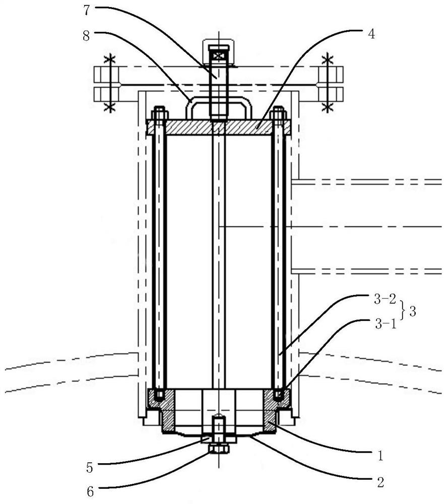
[0015] Embodiment 1, a constant velocity nozzle for a thermal deaerator in this embodiment includes a valve seat 1, a disc 2, at least two connecting rods 3 and a valve cover 4;

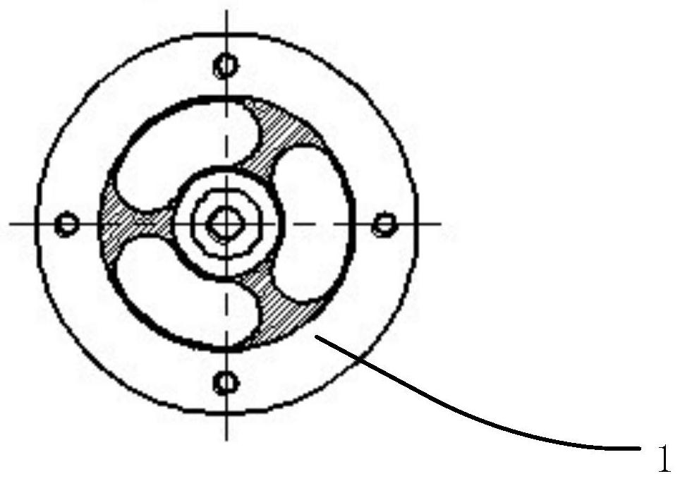
[0016] The valve seat 1 is annular, and the middle part of the valve seat 1 is provided with a disc support boss, and the side wall of the disc support boss is connected and fixed with the inner side wall of the valve seat 1 through connecting ribs;

[0017] The disc 2 is located under the valve seat 1, the center of the disc 2 is fixed to the bottom of the disc support boss, and the edge of the disc 2 is closely attached to the bottom of the valve seat 1;

[0018] The valve cover 4 is located above the valve seat 1 , and the valve cover 4 is fixed to the valve seat 1 through at least two connecting rods 3 .

[0019] Specifically, the valve seat 1, the disc 2, at least two connecting rods 3 and the valve cover 4 are all made of stainless steel.

[0020] like figure 2 As shown, there are at least t...


PUM


Abstract

The invention discloses a constant-speed nozzle for a thermal deaerator, particularly a nozzle for spraying water to a thermal deaerator, and aims to solve the problems that existing constant-speed nozzles are complex in structure, and the spraying effect and the heat and mass transfer performance are reduced under the load of a certain range. The disclosed constant-speed nozzle comprises a valveseat, a disc, at least two connecting rods and a valve cover, wherein the valve seat is annular, a disc supporting boss is arranged in the middle of the valve seat, the side wall of the disc supporting boss is fixedly connected with the inner side wall of the valve seat through a connecting rib, the disc is located below the valve seat, the center of the disc is fixed to the bottom of the disc supporting boss, the edge of the disc is tightly attached to the bottom of the valve seat; the valve cover is located above the valve seat and fixed to the valve seat through the at least two connectingrods.

Description

technical field [0001] The invention relates to a deaerator assembly, in particular to a nozzle for spraying water to a thermal deaerator. Background technique [0002] The built-in deaeration equipment uses thermal method to remove dissolved non-condensable gas in water, thereby improving the quality and temperature of boiler feed water. It is an effective equipment for thermal deaeration, and it is also a high-parameter and large-capacity (300MW and above) generator set boiler and Indispensable equipment in the water supply system of nuclear power units. The constant speed nozzle has high-quality spray effect and good heat and mass transfer performance under various loads. It is a key component of the built-in oxygen removal equipment, which directly affects the output of the equipment, the temperature of the outlet water, and the oxygen content. Safety and stability of equipment operation. [0003] The structure of the existing constant-velocity nozzle is complex, and u...

Claims


Application Information

Patent Timeline
IPC IPC(8): C02F1/20F22D1/50C02F103/02
CPCC02F1/20F22D1/50C02F2103/02
Inventor 邓剑虹杨军国金莲刘博张小波李凤梅章岱超韩健邱平吕永柱腾飞苏雪刚卫乐
Owner HARBIN BOILER
Why Eureka
Try Eureka