Heat pump heating system based on heating pipe network

A heating pipe network and heating system technology, which is applied in hot water central heating systems, heating systems, household heating and other directions, can solve the difficulty of network access in new communities, the saturated transmission and distribution capacity of heating pipe networks, and the low utilization rate of heating water energy. and other problems, to achieve the effect of improving energy utilization, realizing heat recovery, and being easy to implement

Active Publication Date: 2020-09-22
TONGJI UNIV
View PDF11 Cites 0 Cited by
  • Summary
  • Abstract
  • Description
  • Claims
  • Application Information

AI Technical Summary

Problems solved by technology

[0005] The purpose of the present invention is to make full use of the waste heat in the heating pipe network system, solve the problems of saturated transmission and distribution capacity of the current heating pipe network, difficulty in connecting new communities to the network, and low energy utilization rate of the original heating water, and further provide a non-regional And the technical scheme of heating capacity expansion based on the transmission and distribution capacity of the existing heating pipeline network under climate constraints

Method used


Image

  • Heat pump heating system based on heating pipe network
  • Heat pump heating system based on heating pipe network
  • Heat pump heating system based on heating pipe network

Examples


Embodiment 1

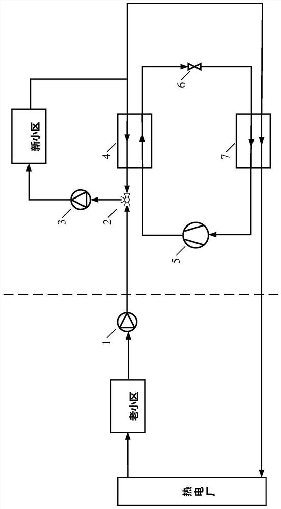
[0052] In this embodiment, it is a structural schematic diagram of heat pump + mixed water mode to realize heat recovery and heating, as shown in figure 2 shown, including:

[0053] Refrigerant circulation circuit: the condenser 4, throttling device 6, evaporator 7 and compressor 5 are connected in sequence through refrigerant pipes.

[0054] Heating water circulation loop: the inlet of the first water pump 1 is connected to the return pipe of the old community through water pipes, the first interface, the second interface, and the third interface of the water mixing valve 2 are respectively connected to the outlet of the first water pump 1 and the inlet of the second water pump 3 And the condenser 4 is connected through water pipes, the outlet of the second water pump 3 is connected with the water supply pipe of the new community through water pipes, the condenser 4, the evaporator 7, and the return water pipes of the new community are respectively connected to the three int...

Embodiment 2

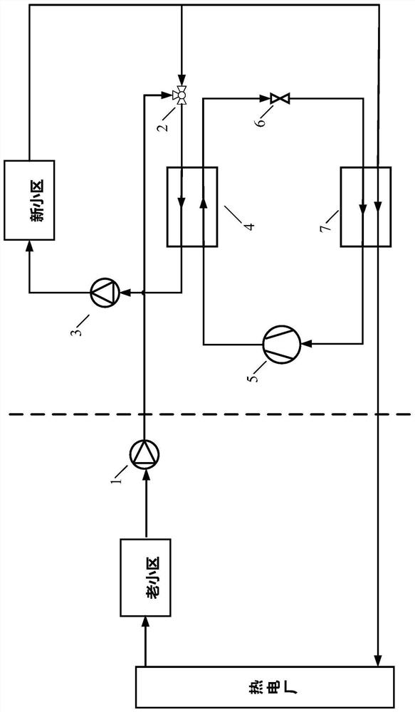
[0060] In this embodiment, it is a schematic structural diagram of using mixed water + heat pump mode to realize regenerative heating, as shown in image 3 As shown, the difference between it and Embodiment 1 is that the three ports of the water mixing valve are changed to be connected to the condenser 4, the first water pump 1, and the tee connecting the return pipe of the new community to the evaporator 7 through water pipes.

[0061] The difference from Example 1 during operation is that the medium-temperature water after the heating in the old district is changed to the medium-temperature water after the heating in the new district is mixed first and then enters the condenser 4 for heating.

Embodiment 3

[0063] In this embodiment, it is a schematic diagram of the structure of heat pump + plate heat exchanger to realize heat recovery and heating, as shown in Figure 4 shown.

[0064] Refrigerant circulation circuit: same as embodiment 1.

[0065] Heating water circulation loop: There are two heating water circulation loops: the heating water circulation loop and the new community water supply circulation loop. In the heating water circulation loop, the inlet and outlet ends of the first water pump 1 are respectively connected to the return water pipe of the old community and the evaporator 7 through water pipes. Plate heat exchange The evaporator 8 is respectively connected with the evaporator 7 and the return pipe of the heating pipe network through water pipes; in the water supply circulation loop of the new residential area, the inlet port of the second water pump 3, the condenser 4 and the plate heat exchanger 8 are respectively connected with the three interfaces of the te...


PUM


Abstract

The invention relates to a heat pump heating system based on a heating pipe network. The heat pump heating system based on the heating pipe network comprises a refrigerant circulation loop, a heatingwater circulation loop and a new residential area water supply circulation loop, wherein hot water in the heating water circulation loop is output by a thermal power plant, flows through an old residential area heating pipe network, and finally flows back to the thermal power plant, and the heating water circulation loop provides heat for the new residential area water supply circulation loop in amanner of direct connection or indirect heat exchanger; and the refrigerant circulation loop is connected with the heating water circulation loop and the new residential area water supply circulationloop in a manner of heat exchange separately, so that heat in the heating water circulation loop is recovered, and the new residential area water supply circulation loop is heated. Compared with theprior art, according to the heat pump heating system based on the heating pipe network, waste heat in the heating pipe network is subjected to secondary recovery, and converted to high-temperature heat energy on the basis of the characteristics of the heat pump system, so that capacity expansion can be realized in the case of not changing the transportation and distribution capacity of the heatingpipe network, and the thermal comfort of a user while using can also be ensured; and moreover, the scheme is not limited by regions and weather.

Description

technical field [0001] The invention relates to the field of heat pump systems, in particular to a heat pump heating system based on a heating pipe network. Background technique [0002] At present, the schematic diagram of the urban heating pipe network commonly used in the northern heating system is as follows: figure 1 As shown, the thermal power plant uses waste heat to produce hot water for heating and transports it to the heat-using community for heating through the heating pipe network. After the heating is completed, the return water needs to be cooled by the cooling tower to below 15°C before entering the thermal power plant for heating. The system mainly has the following contradictions in actual use: on the one hand, the heating equipment in the old residential area is outdated, and the return water temperature is high (around 40-50°C), and the thermal power plant needs to be cooled to a lower temperature before reuse, resulting in a lot of energy waste. The util...

Claims


Application Information

Patent Timeline
IPC IPC(8): F24D3/18F24D3/10
CPCF24D3/1058F24D3/18F24D2200/12F24D2200/13
Inventor 曹祥靳文睿张靖张春路
Owner TONGJI UNIV
Why Eureka
Try Eureka