Device and method for measuring the outer diameter of a thin-walled bearing ring
A thin-walled bearing and measuring device technology, applied in the direction of measuring device, mechanical measuring device, mechanical diameter measurement, etc., can solve the problem that the measuring head does not point to the bearing ring, the thin-walled bearing ring is contacted and deformed, and cannot face the bearing ring. and other problems, to achieve the effect of reducing the force measurement error, eliminating the elastic deformation of the extrusion, and reducing the self-weight error
- Summary
- Abstract
- Description
- Claims
- Application Information
AI Technical Summary
Problems solved by technology
Method used
Image
Examples
Embodiment 1
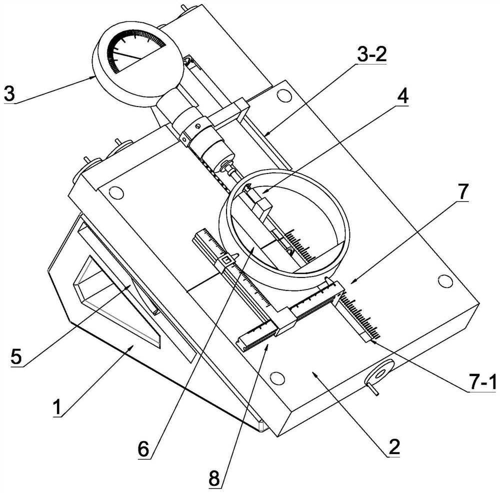
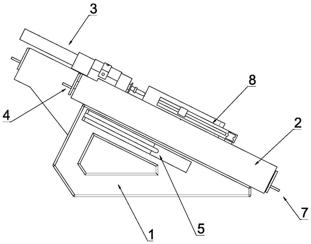
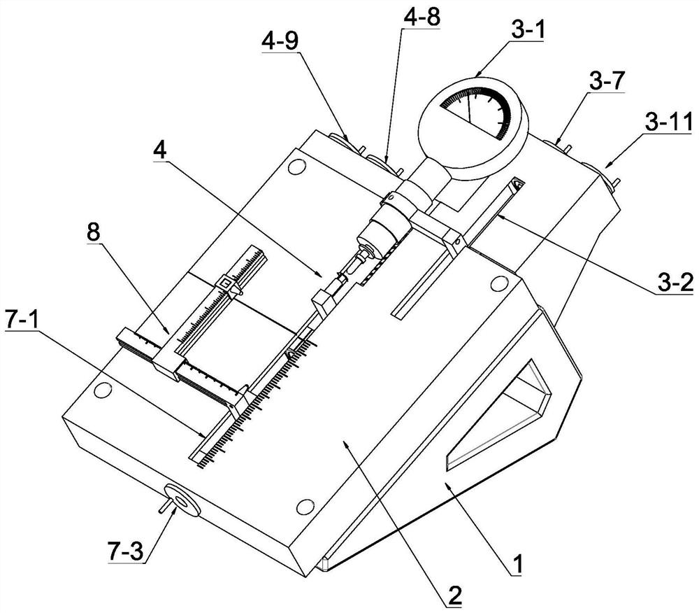
[0054] see Figure 1-Figure 5 , this embodiment discloses an outer diameter measuring device of a thin-walled bearing ring, which includes a support frame 1, a worktable 2 inclinedly arranged on the support frame 1, and a worktable 2 arranged on the worktable 2 for measuring the thickness of the thin-walled bearing ring. A positioning mechanism for positioning the bearing ring, a measuring mechanism for measuring the outer diameter of the thin-walled bearing ring to be measured 3, a counter-measuring mechanism for offsetting the measuring force generated by the measuring mechanism 3 for the thin-walled bearing ring to be measured 4, A ring-shaped electromagnetic mechanism 5 arranged at the lower end of the worktable 2 and a reinforcing rib 6 for preventing elastic deformation of the thin-walled bearing ring by the positioning mechanism; the worktable 2 is provided with a measurement center.
[0055] see Figure 1-Figure 5 , the positioning mechanism includes a Y-axis positionin...
Embodiment 2
[0088] see Figure 14, this embodiment is the same as the other structures of Embodiment 1, the difference is that the X-axis adjustment mechanism includes an X-axis adjustment rocker 8-6 that is rotated and arranged on the side of the worktable 2, and the upper edge of the worktable 2 is set. The X-axis guide groove 8-7 extending in the X-axis direction and the X-axis sliding block 8-8 slidingly matched with the X-axis guide groove 8-7, the X-axis adjustment rocker 8-6 and the X-axis The sliding blocks 8-8 are connected by the X-axis screw drive assembly. The X-axis screw drive assembly is designed with reference to the above-mentioned Y-axis screw 7-5 drive assembly. The X-axis positioning rod 8-1 is connected to the X-axis screw drive assembly. The shaft sliding block 8-8 is fixedly connected, and the ball head of the X-axis positioning rod 8-1 faces the measurement center. By setting the above mechanism, manually rotating the X-axis adjustment rocker 8-6 drives the X-axis...
Embodiment 3
[0090] This embodiment is the same as the other structures of Embodiment 1, except that the Y-axis screw 7-5 transmission assembly, the measuring screw 3-5 transmission assembly and the positioning screw transmission assembly can all be driven by synchronous belts Way.
PUM
 Abstract
Description
Claims
Application Information
 - R&D
- Intellectual Property
- Life Sciences
- Materials
- Tech Scout
- Unparalleled Data Quality
- Higher Quality Content
- 60% Fewer Hallucinations
Browse by: Latest US Patents, China's latest patents, Technical Efficacy Thesaurus, Application Domain, Technology Topic, Popular Technical Reports.
© 2025 PatSnap. All rights reserved.Legal|Privacy policy|Modern Slavery Act Transparency Statement|Sitemap|About US| Contact US: help@patsnap.com


