
Radio frequency direction finding method and system

A radio frequency and vector technology, applied in the field of radio frequency direction finding methods and systems, can solve problems such as insufficient utilization of hardware resources, insufficient application of antennas, complex calculations, etc., avoid logical judgment and other operations, avoid phase ambiguity problems, and have high precision Effect

Active Publication Date: 2020-09-22
SOUTHWEST CHINA RES INST OF ELECTRONICS EQUIP
View PDF16 Cites 4 Cited by
  • Summary
  • Abstract
  • Description
  • Claims
  • Application Information

AI Technical Summary

Problems solved by technology

For the above-mentioned multi-baseline, parallel baseline, extended baseline, virtual baseline and other defuzzification methods, the higher the accuracy, the more the number of antennas, but only part of the antennas are used for angle measurement, and the rest of the antennas are only to exclude multi-values, which leads to a decrease in hardware resources. Underutilized to improve angle measurement accuracy with additional antennas
[0007] In short, the above method has steps such as search, clustering threshold setting, logical judgment, etc., and there are problems such as complex calculation and insufficient antenna application, resulting in low accuracy.

Method used


Image

  • Radio frequency direction finding method and system
  • Radio frequency direction finding method and system
  • Radio frequency direction finding method and system

Examples


Embodiment Construction

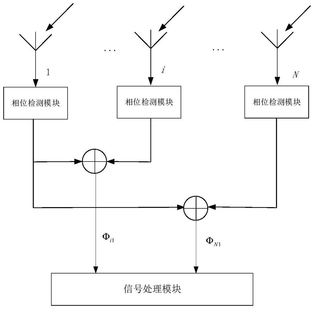
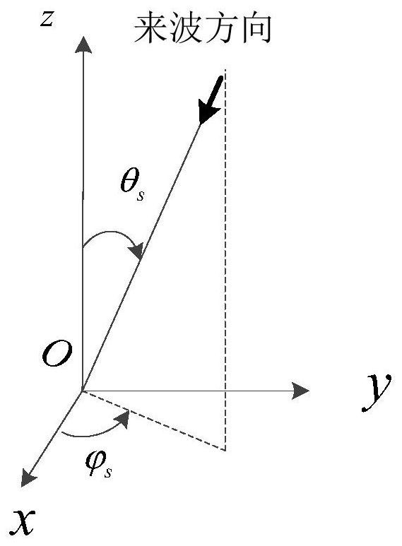
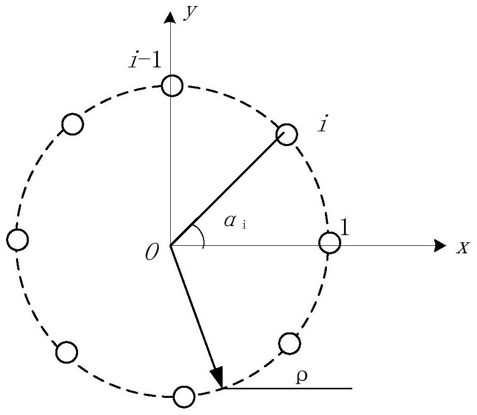
[0055] The present invention will be further described below in conjunction with the accompanying drawings. The invention provides a simple and high-precision two-dimensional incident angle measurement method and system. The advantage of this method lies in the use of complex operations, thereby avoiding the phase ambiguity problem; the use of the information of all antennas on the circular array improves the accuracy of direction finding; the use of iterative algorithms avoids operations such as logical judgment; figure 1 The main function of the radio frequency receiving system shown is to convert the extracted space electromagnetic waves into phases reaching different antennas. The direction finding system used can be, but not limited to figure 1 form. N in the figure is the number of antennas, and a phase detector is used for phase detection to obtain the phase difference between each antenna and one of the antennas. Without loss of generality, each antenna performs phas...


PUM


Abstract

The invention provides a radio frequency direction finding method. The method comprises the following steps of, for an N-element uniform circular array antenna, obtaining a voltage phase difference between each path of antenna and a first path of antenna through a phase discriminator; recording each phase difference as an initial phase difference when an incoming wave enters the circular array antenna at an elevation angle of 0 degree; constructing a complex number corresponding to each antenna according to the voltage phase difference and the initial phase difference; calculating a theoretical phase difference between each antenna and the first antenna according to the elevation angle and the azimuth angle; introducing a vector X and a direction vector G, calculating the difference between the iteration times k+1 and a two-dimensional incident angle of the iteration times k by combining the elevation angle and the azimuth angle of the two-dimensional incident angle of the iteration times k+1 calculated by the constructed complex number, comparing at a threshold value, and entering an output elevation angle and an azimuth angle when the difference is smaller than the threshold value; otherwise, adding 1 to the value of k, and calculating the theoretical phase difference again. The method is advantaged in that complex operation is adopted, a phase ambiguity problem is avoided, direction finding precision is improved, and an iterative algorithm is adopted so that operations such as logic judgment are avoided.

Description

technical field [0001] The invention relates to the technical field of radio monitoring, in particular to a radio frequency direction finding method and system. Background technique [0002] The interferometer direction-finding system belongs to the phase direction-finding system. When the incoming wave arrives at the direction-finding antenna array, the different spatial positions of different antennas lead to different phases of the signals received by each antenna unit to obtain the direction information of the incoming wave. Interferometer direction finding technology has been widely used in the field of passive direction finding because of its high precision, clear principle and wide frequency range. [0003] The phase interferometer is a direction finding method commonly used in the current direction finding system because of its high direction finding accuracy. Due to the simple operation of the linear least squares method, the least squares is used to process the ph...

Claims


Application Information

Patent Timeline
Patent Type & Authority Applications(China)
IPC IPC(8): G01S3/48
CPCG01S3/48Y02D30/70
Inventor 左乐廖骥程鹏李建军成志强王建水聂剑坤应钱诚刘颖张浩斌
Owner SOUTHWEST CHINA RES INST OF ELECTRONICS EQUIP
Learn More