Capacitance detection device
A technology for electrostatic capacitance and detection devices, which is applied in the direction of measuring devices, capacitance measurement, radio wave measurement systems, etc., can solve the problems of decreased detection accuracy and increased detection time of electrostatic capacitance, and achieve the effect of shortening time and reducing detection accuracy
- Summary
- Abstract
- Description
- Claims
- Application Information
AI Technical Summary
Problems solved by technology
Method used
Image

Examples
no. 1 approach >
[0040] Hereinafter, a first embodiment of the capacitance detection device will be described.
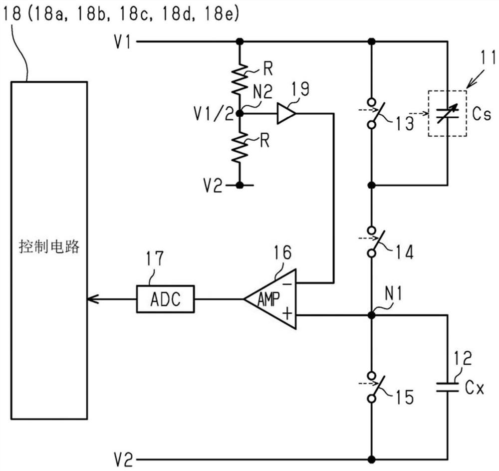
[0041] Such as figure 1 As shown, the electrostatic capacitance detection device includes: a capacitor array 11, a detection capacitor 12 as a detection object of capacitance, a first switch 13, a second switch 14, a third switch 15, a differential amplifier circuit 16 as an amplifier, and an AD conversion circuit. part of the AD conversion circuit 17, and the control circuit 18.
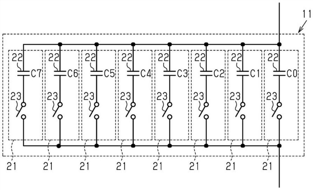
[0042] The capacitor array 11 has a variable combined capacity Cs. That is, if figure 2 As shown, the capacitor array 11 is configured by connecting a plurality of (for example, eight) capacity units 21 in parallel, and the capacity units 21 have capacitors 22 and switches 23 connected in series. The capacities of these plurality of capacitors 22 are set to be different from each other. Specifically, when the capacity of the capacitor 22 with the smallest capacity is represented by C0, the capacities...
no. 2 approach >
[0106] Hereinafter, the second embodiment will be described focusing on differences from the first embodiment with reference to the drawings.
[0107] Figure 5 The electrostatic capacity detection device 30 of this embodiment is shown. In addition, in Figure 5 In, for convenience, for figure 1 The corresponding parts of the shown parts are marked with the same symbols.
[0108] The electrostatic capacitance detection device 30 of the present embodiment is a proximity detection sensor mounted on a vehicle to detect that a person has approached a predetermined part of the vehicle. Specifically, for example, it is a sensor that detects that a person's foot touches the rear of the vehicle, or that a person's hand traces near the sliding door of the vehicle. When the proximity detection sensor detects that a predetermined part of a person, which is a target object, approaches, the opening and closing section of the vehicle is automatically opened by an electronic control unit...
no. 3 approach >
[0134] Hereinafter, the third embodiment will be described focusing on differences from the first embodiment with reference to the drawings.
[0135] Figure 9 The sequence of processing executed by the control circuit 18 is shown. Figure 9 The shown processing is repeatedly executed by the control circuit 18 at a predetermined cycle. In addition, in Figure 9 In, for convenience, for Figure 6 The processes corresponding to the shown processes are denoted by the same step numbers.
[0136] exist Figure 9 In the series of processes shown, when the process of S28 ends, the control circuit 18 substitutes the differential voltage ΔV obtained in the process of S26 into the differential voltage ΔVa ( S50 ). Then, the control circuit 18 waits until the predetermined time T1 elapses (S52: NO). Here, the specified time T1 is set as a ratio Figure 9 The cycle of processing repeats at short intervals. Then, when the predetermined time T1 elapses (S52: Yes), the control circui...
PUM
 Abstract
Description
Claims
Application Information
 - R&D
- Intellectual Property
- Life Sciences
- Materials
- Tech Scout
- Unparalleled Data Quality
- Higher Quality Content
- 60% Fewer Hallucinations
Browse by: Latest US Patents, China's latest patents, Technical Efficacy Thesaurus, Application Domain, Technology Topic, Popular Technical Reports.
© 2025 PatSnap. All rights reserved.Legal|Privacy policy|Modern Slavery Act Transparency Statement|Sitemap|About US| Contact US: help@patsnap.com