Exposure method for color film substrate

A technology of color film substrate and exposure method, which is applied in the direction of originals, optics, and optomechanical equipment for photomechanical processing, which can solve problems such as mechanical errors, unfavorable processing, and light leakage, and achieve lower precision requirements and lower alignment accuracy , cost reduction effect

Pending Publication Date: 2020-09-22
信利(仁寿)高端显示科技有限公司
View PDF4 Cites 1 Cited by
  • Summary
  • Abstract
  • Description
  • Claims
  • Application Information

AI Technical Summary

Problems solved by technology

[0003] In the prior art, a high-precision mask is used to expose the color filter layer from one side of the black matrix layer (the front side of the substrate). Due to process fluctuations and mechanical errors in actual operation, the accuracy cannot reach 100%. In order to completely cover the black matrix In the opening area of ​​the layer, the exposed area needs to be larger than the opening area of ​​the black matrix layer, which leads to the residual RGB PR glue on the upper surface of the black matrix layer close to the opening area (usually called Data line and Gate line), The formation of a high level difference is not conducive to post-process processing, so it is necessary to add an additional OC flat layer
[0004] Therefore, in order to reduce the step difference, the precision of the mask plate needs to be higher, otherwise there will be a risk of light leakage; if the step difference is particularly large, it will cause the problem that it cannot be completely flat even if the OC flat layer is added
If the thickness of the OC flat layer is increased to improve the flat effect, the cost will increase and the transmittance will increase
In addition, the method of front-side exposure of the substrate may also cause undercut phenomenon after the development of the color filter layer. The undercut phenomenon means that when exposed from the front, the upper and lower parts of the RGB adhesive layer have less curing strength than the upper part due to the exposure intensity. Strong, the phenomenon that the lower part is hollowed out after developing

Method used


Image

  • Exposure method for color film substrate

Examples


Embodiment Construction

[0021] The present invention will be described in detail below with reference to the drawings and embodiments. Examples of the embodiments are shown in the drawings, wherein the same or similar reference numerals represent the same or similar elements or elements with the same or similar functions. The embodiments described below by referring to the figures are exemplary and are intended to explain the present invention and should not be construed as limiting the present invention.

[0022] In describing the present invention, it should be understood that the terms "length", "width", "upper", "lower", "front", "rear", "left", "right", "vertical", The orientations or positional relationships indicated by "horizontal", "top", "bottom", "inner", "outer", etc. are based on the orientation or positional relationships shown in the drawings, and are only for the convenience of describing the present invention and simplifying the description, and It is not to indicate or imply that th...


PUM


Abstract

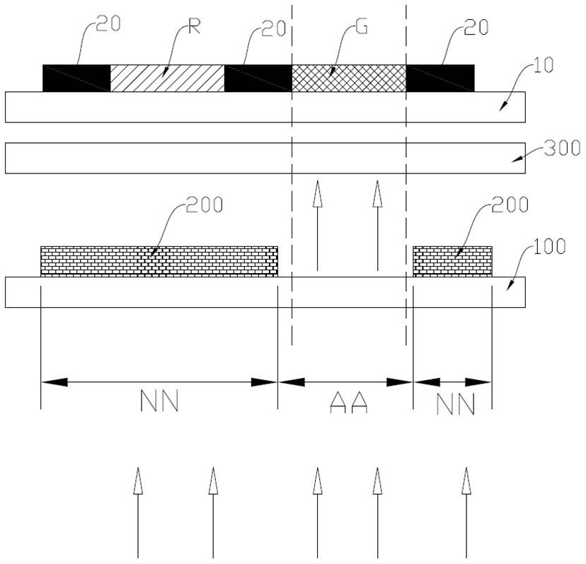
The invention discloses an exposure method for a color film substrate. The method comprises the following steps of S1, providing a substrate, forming black matrix layers at intervals on an upper surface of the substrate, and taking a region without the black matrix layers as an opening region; S2, covering an upper surface of the opening region of the substrate and an upper surface of the black matrix layer with a negative photosensitive adhesive layer; S3, providing a mask version body of which the upper surface is provided with a shielding layer, forming the mask version body below the substrate, and arranging the shielding layer towards the substrate; and S4, exposing light beams perpendicular to a plane of a mask plate penetrating through the region, not provided with the shielding layer, of the mask plate body from the lower portion of the mask plate body, and the photosensitive adhesive layer so that the color filter layer is formed through the process including development. Themethod is advantaged in that the mask plate is formed on a lower surface of the substrate, the shading property of a black matrix layer on an upper surface of the substrate is utilized, so segment difference is eliminated, and the precision requirement of the mask plate and the alignment precision requirement of an exposure machine are reduced.

Description

technical field [0001] The invention relates to the technical field of manufacturing a color filter substrate in a liquid crystal display, and more particularly relates to an exposure method for a color filter substrate. Background technique [0002] Such as figure 1 As shown, a liquid crystal display generally includes an array substrate and a color filter substrate arranged in a box, wherein the color filter substrate includes a base, a black matrix (BM) layer on the base, a color filter layer (RGB) on the black matrix layer and the base ), and an insulating film layer (OC) on the color filter layer, wherein the color filter layer fills the opening area of ​​the black matrix layer. The production of the color film substrate is usually to first make a black matrix layer on the base, and then apply RGB glue on the basis of the black matrix layer. The illuminated part is removed, and then the light-shielding layer of the mask is used to determine the remaining part and the ...

Claims


Application Information

Patent Timeline
Patent Type & Authority Applications(China)
IPC IPC(8): G02F1/1335G03F7/00G03F1/00
CPCG02F1/133516G02F1/133512G03F7/0007G03F1/00
Inventor 兰沈凯郭启好刘杰吴杰明
Owner 信利(仁寿)高端显示科技有限公司
Why Eureka
Try Eureka