Intelligent motor controller

A technology of intelligent controllers and control boards, applied in the direction of electric solid-state devices, circuits, electrical components, etc., can solve the problems that the controller cannot withstand large current output, the power of the motor controller decreases, and the temperature of the motor controller is high, so as to improve heat dissipation effect, flow rate increase, effect of enhanced heat convection intensity

Active Publication Date: 2020-09-22
江门市力丰电机有限公司
View PDF9 Cites 3 Cited by
  • Summary
  • Abstract
  • Description
  • Claims
  • Application Information

AI Technical Summary

Problems solved by technology

The traditional motor controller mainly dissipates heat from one side of the driver board, and the heat dissipation effect is not good, which leads to the temperature of the motor controller being too hig

Method used


Image

  • Intelligent motor controller
  • Intelligent motor controller
  • Intelligent motor controller

Examples


Embodiment 1

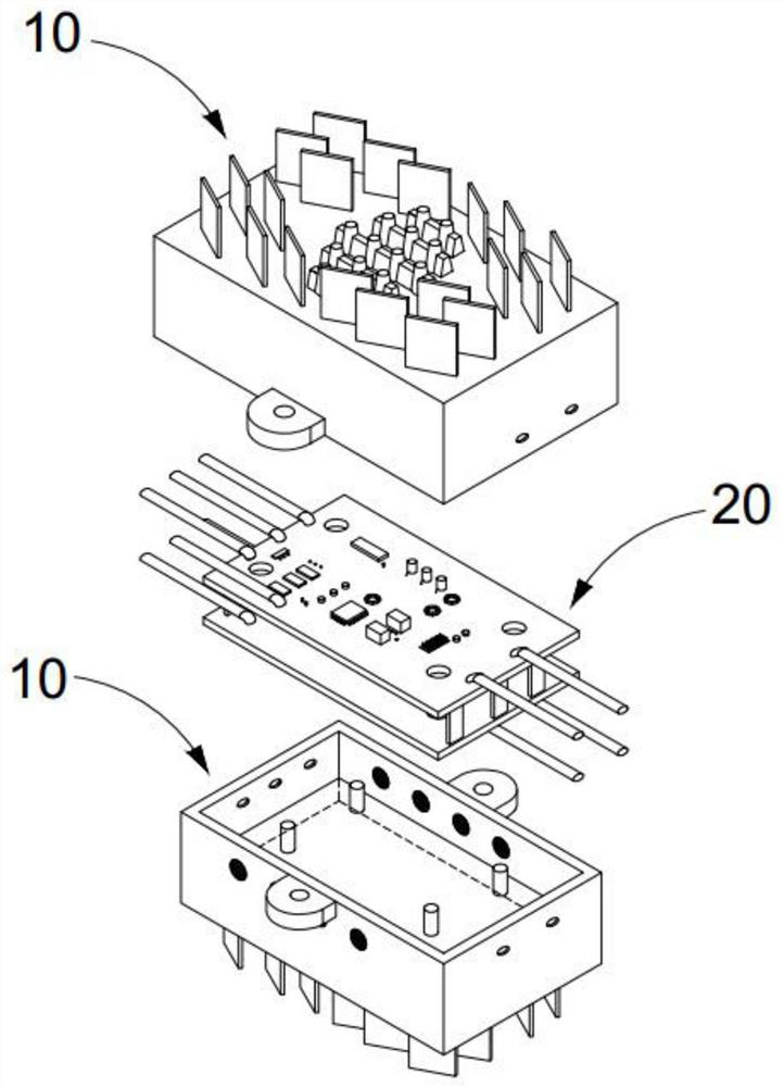
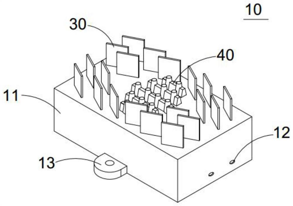
[0047] See attached Figure 1-9As shown, a motor intelligent controller includes: a control board 20, the upper and lower ends of the control board 20 are equipped with a heat sink 10, the heat sink 10 includes a heat dissipation housing 11, and the control board 20 is located in the heat dissipation housing 11; 11 has a heat dissipation surface, the middle part of the heat dissipation surface is provided with a heat dissipation strip 40, and the two sides of the heat dissipation strip 40 in the middle part of the heat dissipation surface are arranged at intervals horizontally and the length of the heat dissipation strips 40 is gradually reduced, and the heat dissipation surface is provided with heat dissipation fins 30 arranged vertically to the heat dissipation surface , the heat dissipation fins 30 are symmetrically arranged on the side of the heat dissipation strip 40, and are inclined relative to the heat dissipation strip 40. The heat dissipation fins 30 are used to guide...

Embodiment 2

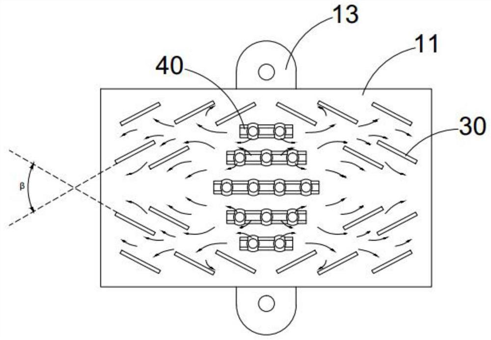
[0078] This embodiment is optimized as follows on the basis of Embodiment 1: the heat dissipation surface has a symmetrical center line of the long side and a symmetrical center line of the short side, and the cooling strip 40 is arranged parallel to the symmetrical center line of the long side or the symmetrical center line of the short side. The sheet 30 has an included angle with the symmetrical center line of the long side or the symmetrical center line of the short side, and the included angle is an acute angle. There is no limit to the included angle of the radiating fins 30 oppositely arranged on both sides. By limiting the relative included angle of the radiating fins 30, the arrangement scheme of the radiating fins 30 is optimized, so that the airflow passing through the heat-dissipating surface in different directions can effectively make the airflow in the middle of the heat-dissipating surface. A certain aggregation effect is formed, and the upward flow rate of the ...


PUM


Abstract

The invention discloses an intelligent motor controller, and belongs to the technical field of motor control. The intelligent motor controller comprises a control panel, wherein heat dissipation pieces are arranged at the upper end and the lower end of the control panel, each heat dissipation piece comprises a heat dissipation shell, and the control panel is arranged in the heat dissipation shell;the heat dissipation shell is provided with a heat dissipation surface, heat dissipation strips are arranged in the middle of the heat dissipation surface; the heat dissipation strip in the middle ofthe heat dissipation surface are horizontally arranged at intervals, the lengths of the heat dissipation strips decrease progressively, the heat dissipation surface is provided with heat dissipationfins perpendicular to the heat dissipation surface, the heat dissipation fins are symmetrically arranged on the sides of the heat dissipation strips and are obliquely arranged relative to the heat dissipation strips, the heat dissipation fins are used for guiding airflow on the two sides of the heat dissipation surface to the heat dissipation strips in the middle of the heat dissipation surface, and the height of the heat dissipation fins is greater than that of the heat dissipation strips. According to the invention, the motor controller has the advantages of fast heat leading-out speed, highheat conduction efficiency, high heat dissipation efficiency, balanced heat dissipation and strong external interference resistance, and effectively prevents dust from entering the controller and electromagnetic noise pollution.

Description

technical field [0001] The invention belongs to the technical field of motor control, and in particular relates to an intelligent motor controller. Background technique [0002] A general motor controller consists of a control board, a driver board and a heat sink. Because power devices (such as MOSFETs or IGBTs) are installed on the driver board, and power devices generally generate heat, it is necessary to design a certain heat dissipation structure to transfer the heat generated inside. The traditional motor controller mainly dissipates heat from one side of the driver board, and the heat dissipation effect is not good, which leads to the temperature of the motor controller being too high during operation, and the service life is not long; at the same time, the poor heat dissipation makes the controller unable to withstand large current output, resulting in motor control. The power of the device drops. Contents of the invention [0003] The purpose of the present inve...

Claims


Application Information

Patent Timeline
IPC IPC(8): H01L23/34H01L23/367H01L23/40H01L23/467H01L23/473
CPCH01L23/3672H01L23/40H01L23/473H01L23/467H01L23/34
Inventor 朱冬祥
Owner 江门市力丰电机有限公司
Why Eureka
Try Eureka