
Series-fed microstrip antenna

A microstrip antenna and antenna technology, which is applied to antennas, resonant antennas, antenna grounding devices, etc., can solve the problems of low radiation efficiency and achieve the effect of improving radiation efficiency.

Pending Publication Date: 2020-09-22
WHST CO LTD
View PDF0 Cites 3 Cited by
  • Summary
  • Abstract
  • Description
  • Claims
  • Application Information

AI Technical Summary

Problems solved by technology

[0004] In view of this, the embodiment of the present invention provides a serial-fed microstrip antenna to solve the problem that the serial-fed microstrip antenna in the prior art tends to generate additional insertion loss and low radiation efficiency

Method used


Image

  • Series-fed microstrip antenna

Examples


Embodiment Construction

[0020] In the following description, specific details such as specific system structures and technologies are presented for the purpose of illustration rather than limitation, so as to thoroughly understand the embodiments of the present invention. It will be apparent, however, to one skilled in the art that the invention may be practiced in other embodiments without these specific details. In other instances, detailed descriptions of well-known systems, devices, circuits, and methods are omitted so as not to obscure the description of the present invention with unnecessary detail.

[0021] In order to illustrate the technical solutions of the present invention, specific examples are used below to illustrate.

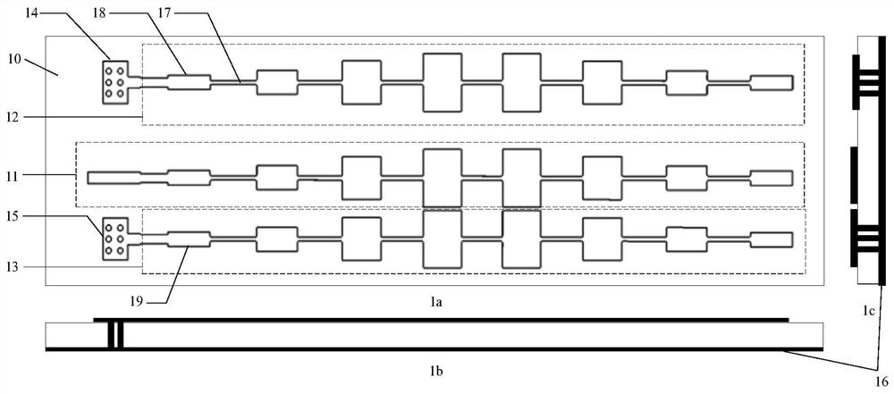
[0022] see figure 1 , which shows a schematic structural diagram of the serial-fed microstrip antenna provided by the embodiment of the present invention, including the main view figure 1 a. Side view figure 1 b and side view figure 1 c, specifically may include:

...


PUM


Abstract

The invention is applicable to the technical field of radar antennas, and provides a series-fed microstrip antenna, which comprises a series-fed antenna, a first coupled antenna and a second coupled antenna which are arranged on the front surface of a substrate, a grounding metal plate arranged on the back surface of the substrate, and a first grounding hole and a second grounding hole which penetrate through the substrate, wherein the first coupled antenna and the second coupled antenna are arranged on the two sides of the series-fed antenna in parallel, and are separated from the series-fedantenna by a first preset distance and a second preset distance respectively, and the first coupled antenna and the second coupled antenna are respectively connected with the grounding metal plate through the first grounding hole and the second grounding hole. According to the invention, the maximum beam pointing direction of the series-fed antenna can be changed, the 3db beam width is broadened,no extra insertion loss is generated, and the radiation efficiency of the antenna is effectively improved.

Description

technical field [0001] The invention belongs to the technical field of radar antennas, in particular to a series-fed microstrip antenna. Background technique [0002] Compared with the traditional microstrip antenna, the series-fed microstrip antenna has the characteristics of compact structure, easy integration, and easier realization of narrow beam and high gain, and has become a research hotspot in the field of radar antennas. [0003] Since the traditional series-fed microstrip antenna has only one antenna unit, the maximum beam pointing in the horizontal direction is fixed, and the 3dB beam width is about 70°-80°. In the prior art, multiple serial-fed microstrip antennas are usually combined into an array antenna, and combined with a relatively complex feed network to change the maximum beam direction of the serial-fed microstrip antenna and widen the 3dB beamwidth, but this method will generate additional Insertion loss reduces the radiation efficiency of the antenna....

Claims


Application Information

Patent Timeline
Patent Type & Authority Applications(China)
IPC IPC(8): H01Q1/36H01Q1/38H01Q1/48H01Q1/50H01Q9/04H01Q13/08H01Q21/08H01Q21/24
CPCH01Q1/36H01Q1/38H01Q1/48H01Q1/50H01Q9/0407H01Q13/08H01Q21/08H01Q21/24
Inventor 宋跃张领飞秦屹
Owner WHST CO LTD
Learn More