Rapid multi-cable synchronous laying and withdrawing device

A cable and fast technology, applied in the direction of cable laying equipment, etc., can solve the problems that cannot satisfy the rapid and automatic laying and withdrawal of multi-cables, cannot satisfy the synchronous retraction of multi-cables, and the long time of cable reel erection, etc., to achieve reduction Effects of manual operation strength, connection time saving, manpower and operation time saving

Pending Publication Date: 2020-09-25
CHINA ELECTRONICS TECH GRP CORP NO 14 RES INST
View PDF3 Cites 5 Cited by
  • Summary
  • Abstract
  • Description
  • Claims
  • Application Information

AI Technical Summary

Problems solved by technology

Conventional cable reels take a long time to erect, have a low degree of automation, and are labor-intensive, which cannot meet the requirements of rapid and automatic laying and withdrawal of multiple cables
[0003] In order to reduce manual labor intensity, there are some automatic laying devices for cables, such as a new type of cable reel with application number: CN201721260073. efficiency and speed, but one cable reel can only accommodate one cable at the same time, which cannot satisfy the synchronous retraction and retraction of multiple cables, and the equipment needs to be connected after the cable is laid; application number: CN201820669554, a diesel engine cable laying device, the patent passed The straightening tube straightens the cable to facilitate cable laying. The motor and tractor are used to realize mechanized cable laying. Although the labor intensity is reduced and the laying efficiency is improved, the device can only accommodate one cable and cannot satisfy multiple cables. Synchronous retraction and retraction, and manual auxiliary wiring is required when the cable is retracted; application number: CN201721746030.2 A self-retractable cable device for laying optical fibers, this patent provides a self-retractable cable device for laying optical fibers, which improves the The efficiency and speed of optical fiber, but only light optical fiber can be retracted and retracted, and it cannot be retracted and retracted for thicker and heavier cables

Method used


Image

  • Rapid multi-cable synchronous laying and withdrawing device
  • Rapid multi-cable synchronous laying and withdrawing device
  • Rapid multi-cable synchronous laying and withdrawing device

Examples


Embodiment Construction

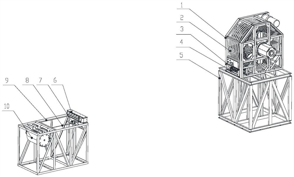
[0028] The specific implementation manners of the present invention will be further described in detail below in conjunction with the accompanying drawings and embodiments. The following examples are only used to illustrate the present invention, but not to limit the scope of the present invention.

[0029] The orientation or position relationship terms such as up, down, left, right, inside, outside, front end, rear end, head, and tail in this application document are established based on the orientation or position relationship shown in the drawings. If the drawings are different, the corresponding positional relationship may also change accordingly, so this should not be understood as limiting the scope of protection.

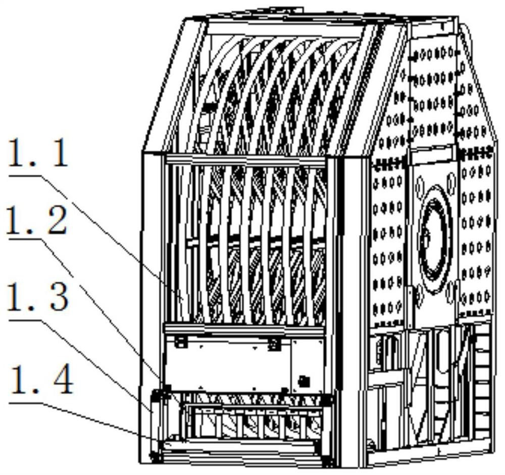
[0030] In the present invention, the terms "installation", "connection", "connection", "connection", "fixation" and so on should be understood in a broad sense, for example, it can be a fixed connection, a detachable connection, or an integrated Connection c...


PUM


Abstract

The invention relates to a rapid multi-cable synchronous laying and withdrawing device. The device comprises a cable reel, electric connectors, a cable tray, a steel wire rope and a winch, wherein thecable reel comprises cable separation reels, and the plurality of cable separation reels are fixed on the cable reel at intervals to divide the cable reel into a plurality of independent grids; a plurality of cables respectively coil in the independent grids; one end of each cable is connected with a collector ring, and the other end of each cable is connected with the corresponding electric connector; the plurality of electric connectors are arranged on the cable tray side by side; the steel wire rope coils in the winch; after the steel wire rope is connected with the cable tray, the winch drives the plurality of cables to be synchronously laid by pulling the steel wire rope and the cable tray; and after the steel wire rope and the cable tray are disconnected, the cable reel can drive the plurality of cables to be synchronously rolled up. According to the rapid multi-cable synchronous laying and withdrawing device, the plurality of cables can be synchronously and rapidly laid and withdrawn, so that the manual operation intensity is alleviated, and the operation time is shortened.

Description

technical field [0001] The invention relates to a cable laying and withdrawing device, in particular to a fast multi-cable synchronous laying and withdrawing device. Background technique [0002] When erecting mobile equipment, it is necessary to connect cables such as control cables and power cables between the equipment. Conventionally, cable reels are used for multi-layer and multi-turn coiling. When connecting cables, each cable is manually pulled out from the cable reel, and then Connect the two ends of the cable to the two devices; when withdrawing the cable, manually disconnect each cable from the device, and then coil the cables one by one onto the cable reel. Conventional cable reels take a long time to erect, have a low degree of automation, and are labor-intensive, which cannot meet the requirements for rapid and automatic laying and withdrawal of multiple cables. [0003] In order to reduce manual labor intensity, there are some automatic laying devices for cabl...

Claims


Application Information

Patent Timeline
Patent Type & Authority Applications(China)
IPC IPC(8): B65H75/42B65H75/44H02G1/06
CPCB65H75/425B65H75/4402B65H2701/34H02G1/06
Inventor 程亚龙唐宝富杨雯陈世荣刘加增娄华威齐佐尹俊亚
Owner CHINA ELECTRONICS TECH GRP CORP NO 14 RES INST
Why Eureka
Try Eureka