
Rotating head spindle of high-speed steel wire braiding machine

A technology of rotary head and braiding machine, which is applied in the direction of braided fabrics, textiles and papermaking, etc. It can solve the problems of unsteady and stable pay-off of frame spindles, inconvenient disassembly and replacement, and no direction positioning, etc., so as to improve production efficiency and product quality. ,Easy pay-off and stable operation

Pending Publication Date: 2020-09-25
XUZHOU HENGHUI BRAIDING MACHINE
View PDF0 Cites 0 Cited by
  • Summary
  • Abstract
  • Description
  • Claims
  • Application Information

AI Technical Summary

Problems solved by technology

[0003] The purpose of the present invention is to provide a rotary head spindle of a high-speed steel wire braiding machine, which solves the problem that the existing frame spindle cannot be set out in a constant and stable manner, has no direction positioning function, and is inconvenient to disassemble and replace

Method used


Image

  • Rotating head spindle of high-speed steel wire braiding machine
  • Rotating head spindle of high-speed steel wire braiding machine
  • Rotating head spindle of high-speed steel wire braiding machine

Examples


Embodiment

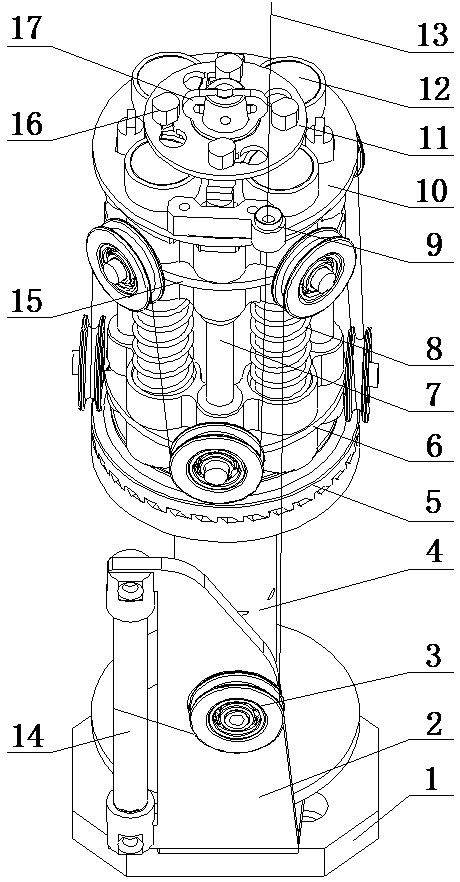
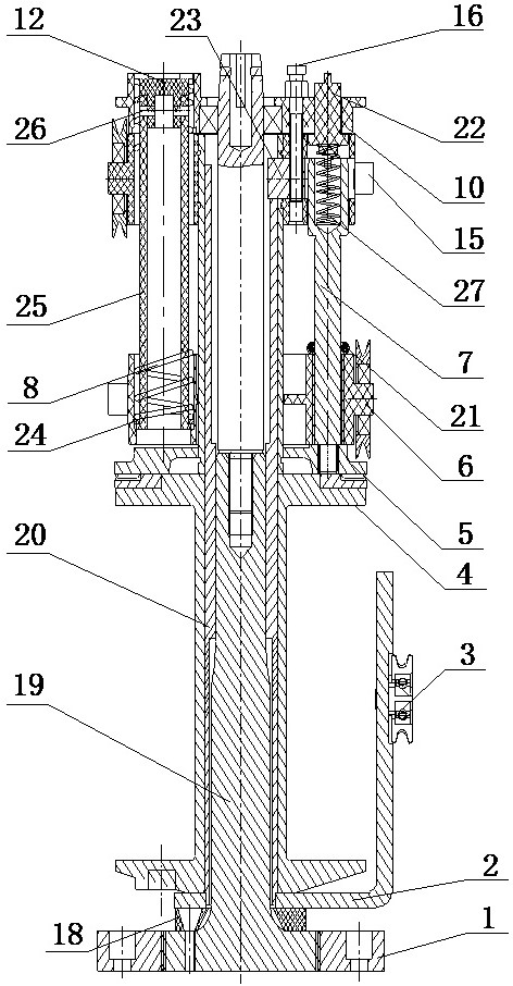
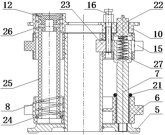
[0029] Embodiment: the rotary head spindle includes: base 1, bobbin 4, pressure cap 17, bobbin shaft spacer 18, bobbin shaft 19, center tube 20 of thread passing frame, guide wheel group, rotary head threading device and thread passing frame components;

[0030] Tighten the bobbin shaft 19 at the center of the base 1, the bobbin shaft spacer 18 is sleeved on the bobbin shaft 19, and fixed on the top of the base 1 with screws, and the bobbin shaft 19 is sleeved with the central tube of the wire stand 20: The bobbin shaft 19 above the bobbin shaft spacer 18 is connected with a bobbin assembly; the bobbin 4 is sleeved on the bobbin shaft 19, which is located at the position where the bobbin shaft 19 is connected with the bobbin assembly The lower end of the rotary head pay-off device is installed on the upper end of the bobbin 4, and the upper end of the rotary head pay-off device is stuck on the card slot of the center tube 20 of the wire frame through the T-shaped pin 23, and p...


PUM


Abstract

The invention relates to a rotating head spindle of a high-speed steel wire braiding machine, and belongs to a high-speed braiding machine spindle. A lower wire wheel seat of the rotating head spindleis located between a middle wire wheel seat and a disc chuck; an upper wire wheel seat is located above the middle wire wheel seat; the upper wire wheel seat and the middle wire wheel seat are fixedby using four retaining screw; four spring guide pillar holes and four fixed shaft holes are equationally and correspondingly arranged on the upper wire wheel seat, the middle wire wheel seat and thelower wire wheel seat; the four fixed shaft holes are alternately arranged among the four spring guide pillar holes; spring guide pillar components are fixed above the upper wire wheel seat through separation blades; pay-off pressure springs are arranged in pay-off pressure spring holes of fixed shafts; rotary pressing caps are arranged in the fixed shaft holes of the upper wire wheel seat and arelocated above the pay-off pressure springs; and rubber rings are arranged on the fixed shafts between the lower wire wheel seat and the middle wire wheel seat. The rotating head spindle of the high-speed steel wire braiding machine has the advantages of easiness in paying off, constancy in tension, smoothness in outgoing wires without breaking the silk wires, long life, low cost and high yarn holding capacity; and the spindle operates stably under left-and-right rotation, the yarn breakage probability is low, and the production efficiency and the product quality are improved.

Description

technical field [0001] The invention relates to a high-speed braiding machine spindle, in particular to a rotary head spindle of a high-speed steel wire braiding machine. Background technique [0002] At present, my country's rubber hose manufacturing is an important part of the rubber industry. There are many kinds of rubber materials and various structures. Among them, the pressure-resistant reinforced rubber hose usually has a braided or wound layer of steel wire, cotton thread or fiber as the skeleton. The skeleton layer of the rubber hose produced at home and abroad is formed by weaving steel wires on the outer surface of the inner rubber of the rubber hose by various steel wire braiding machines. The quality of the hose frame will directly affect the compression, bending and pulse resistance of the hose, while the steel wire tension on the braiding machine spindle is stable, the wires are evenly laid out, and the wires are neatly arranged, which are important factors ...

Claims


Application Information

Patent Timeline
IPC IPC(8): D04C3/00
CPCD04C3/00
Inventor 韩百峰陈兵韩金辉张阳刘建峰韩长江刘同钊仇尊波陈潇雨
Owner XUZHOU HENGHUI BRAIDING MACHINE
Learn More