Prefabricated wall module unit, fabricated composite wall and construction method

A modular unit and composite wall technology, applied to walls, climate change adaptation, building components, etc., can solve problems such as difficult seam processing, general thermal insulation effect, and reduced on-site operations, so as to improve installation quality and installation Efficiency, ensuring the overall strength and thermal insulation performance, the effect of ensuring the overall strength and thermal insulation performance

Pending Publication Date: 2020-09-25
CENT SOUTH UNIV
View PDF0 Cites 7 Cited by
  • Summary
  • Abstract
  • Description
  • Claims
  • Application Information

AI Technical Summary

Problems solved by technology

[0003] 1. At present, the prefabricated walls in the factory are often divided by the size of a bay or the depth, but the weight is heavy, the production cost is high, and the transportation needs to be large-scale transport vehicles, which have high requirements for road traffic conditions. At the same time, long-distance transportation It will also increase the construction cost;
[0004] 2. It is very difficult to deal with the seams after installation, and it is easy to crack after a period of time;
[0005] 3. The heat insulation effect of the external hanging panels of traditional light steel structure buildings is average, and it will also cause a sense of hollowness
On the other hand, at present, light steel-filled concrete walls mostly use concrete pouring on the construction site, which violates the original intention of realizing the industrialization of construction and reducing on-site operations

Method used


Image

  • Prefabricated wall module unit, fabricated composite wall and construction method
  • Prefabricated wall module unit, fabricated composite wall and construction method
  • Prefabricated wall module unit, fabricated composite wall and construction method

Examples


Embodiment 1

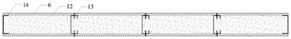
[0048] like figure 1 , a prefabricated wall module unit, including a wall skeleton, a structural panel 6 fixed on the wall skeleton, closing the two opening sides of the wall skeleton, and filling in the closed space formed by the wall skeleton and the structural panel 6 Object 12, the wall skeleton includes an outer frame composed of U-shaped keels 14 and a plurality of vertically arranged C-shaped keels 13 arranged in the outer frame to support the outer frame, and the C-shaped keels 13 are in the outer frame Arranged in parallel along the direction of the wall, four U-shaped keels 14 are connected and fixed from end to end to form a rectangular outer frame. The opening sides of the U-shaped keels 14 are all facing the wall and arranged oppositely. The structural panels 6 are connected and fixed with the U-shaped keels 14 and the C-shaped keels 13 by screws.

[0049] like image 3 As shown, as another structural form of the prefabricated wall module unit, a keel is fixed i...

Embodiment 2

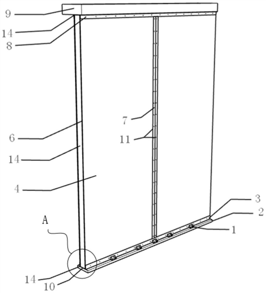
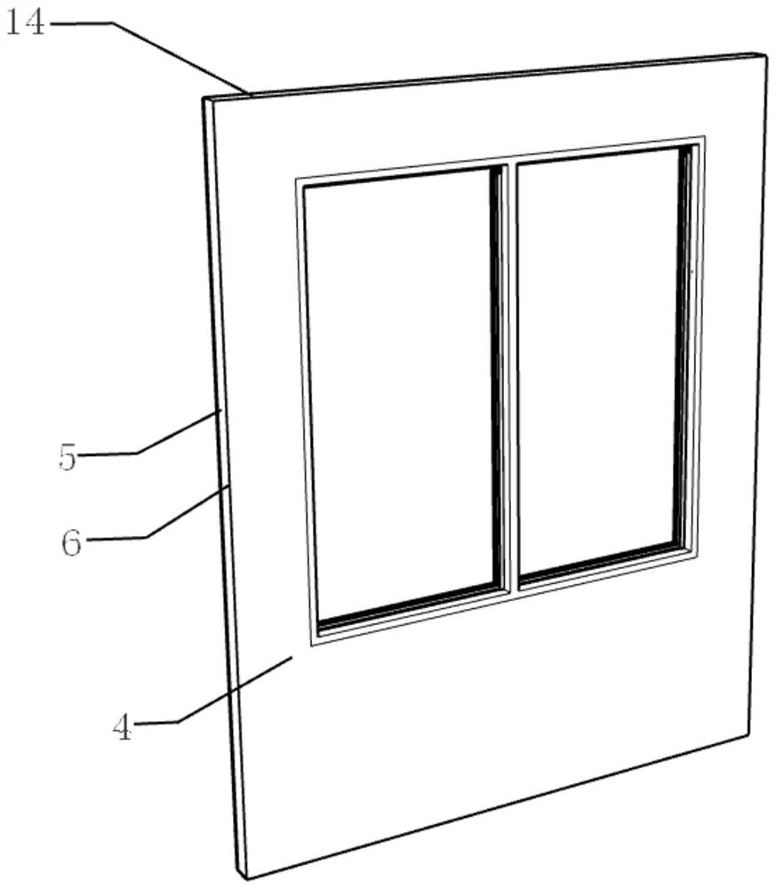
[0054] like Figure 9 As shown, the difference between this embodiment and Embodiment 1 is that the wall skeleton in the prefabricated wall module unit includes I-shaped keels 5 arranged on both sides and U-shaped keels 14 arranged on both sides of the top and bottom. The composed outer frame and a plurality of vertically arranged C-shaped keels 13 arranged in the outer frame to support the outer frame, the C-shaped keels 13 are arranged in parallel along the direction of the wall in the outer frame, and two I-shaped keels 5 Set on the left and right sides of the outer frame, two U-shaped keels 14 are set on the top and bottom sides of the outer frame, the I-shaped keel 5 and the U-shaped keel 14 are connected and fixed from end to end to form a rectangular outer frame, and the C-shaped keel 13 is fixed on the top U-shaped Play a supporting role between the keel 14 and the U-shaped keel 14 at the bottom. The I-shaped keel 5 on both sides of the wall skeleton is relatively arra...


PUM


Abstract

The invention discloses a prefabricated wall module unit, a fabricated composite wall and a construction method. The prefabricated wall module unit is connected with a lower floor slab or a foundation, an upper floor slab or a beam and prefabricated wall module units. The fabricated composite wall is an integrated composite wall formed by connecting the factory prefabricated wall module units through connecting pieces between walls. The prefabricated wall module units can be machined and manufactured in a factory in a standardized mode, the size can be customized according to site and transportation conditions, full-fabricated construction is conducted on site, pouring is not needed, the installation quality and the installation efficiency are improved, full-dry-method installation construction between the prefabricated wall module units is achieved through the fabricated composite wall by means of the different connecting pieces, and the structural safety performance and the heat preservation and insulation performance of the wall are guaranteed through the prefabricated wall module units.

Description

technical field [0001] The invention relates to the field of assembled buildings, in particular to a prefabricated wall module unit, an assembled composite wall and a construction method. Background technique [0002] The following problems exist in the prefabricated wall technology: [0003] 1. At present, the prefabricated walls in the factory are often divided by the size of a bay or the depth, but the weight is heavy, the production cost is high, and the transportation needs to be large-scale transport vehicles, which have high requirements for road traffic conditions. At the same time, long-distance transportation It will also increase the construction cost; [0004] 2. It is very difficult to deal with the seams after installation, and it is easy to crack after a period of time; [0005] 3. Traditional light-steel structure buildings have a mediocre thermal insulation effect of external hanging panels, and can also cause a sense of hollowness. On the other hand, at ...

Claims


Application Information

Patent Timeline
Patent Type & Authority Applications(China)
IPC IPC(8): E04C2/288E04C2/296E04C2/30E04C2/38E04B2/72
CPCE04B2/72E04B2/721E04B2/723E04C2/288E04C2/296E04C2/30E04C2/38E04C2/384Y02A30/244
Inventor 王莉萍胡萌丁发兴余志武
Owner CENT SOUTH UNIV
Why Eureka
Try Eureka