Flared type seamless connector with composite ring

A technology of seamless joints and linings, applied in the direction of pipes/pipe joints/fittings, flange connections, passing components, etc., can solve the problems of easy shrinkage, deformation, corrosion, and heavy weight, and achieve easy installation, transportation, and environmental protection Effect of recycling, simple structure

Pending Publication Date: 2020-09-25
山东三玄橡塑科技股份有限公司
View PDF3 Cites 0 Cited by
  • Summary
  • Abstract
  • Description
  • Claims
  • Application Information

AI Technical Summary

Problems solved by technology

[0004] 1. The flaring seamless joint lined with metal rings (patent number ZL201120415234.4), the disadvantage is that the metal rings are directly exposed, heavy, easy to corrode, not resistant to wear, rubber pads are required for the butt joints between pipes, and the dripping is serious ;
[0005] 2. The flaring seamless joint lined with a rubber layer composite steel ring (ZL201320188506.0). The surface of the rubber-lined steel ring is a rubber layer. When handling or hoisting with a hook, the rubber layer is easy to be scratched, affecting the seal. and shorten wear time;
[0006] 3. The flaring seamless joint lined with plastic ring (ZL201720033234.5), the metal support ring in the inclined groove of the plastic ring lined with the inner liner is too small, the strength is low, the supporting force is small, and it is easy to shrink and deform when squeezed by external force. As a result, the flange is detached, and the joint cannot continue to be used.

Method used


Image

  • Flared type seamless connector with composite ring
  • Flared type seamless connector with composite ring
  • Flared type seamless connector with composite ring

Examples


Embodiment Construction

[0025] The present invention will be further described below in conjunction with the drawings.

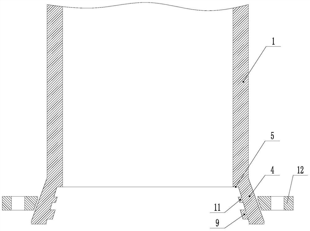
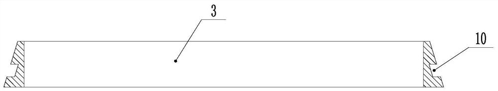
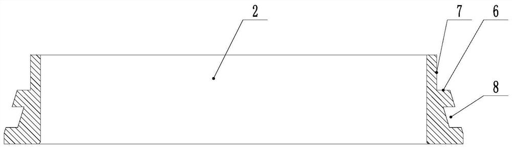
[0026] Such as Figure 1-4 As shown, the flared seamless joint with a composite ring of the present invention includes a connecting pipe 1, a first liner 2 and a second liner 3, and the end of the connecting pipe 1 is provided with a flaring 4, A first shoulder 5 is provided at the joint of the flaring 4 and the connecting pipe 1, one end of the first bushing 2 is provided with a first abutting portion that abuts against the inner wall of the flaring 4, and a second shoulder is provided on the other end Part 6, the second shoulder part 6 is provided with a support part 7 for supporting the second liner 3 on one side, and a second abutting part abutting against the inner wall of the flaring 4 is provided on the outer edge of the second liner 3 , One end of the second backing ring 3 abuts against the second shoulder 6 and the other end abuts against the first shoulder 5; the first abut...


PUM


Abstract

The invention relates to a seamless connector, in particular to a flared type seamless connector with a composite ring. The flared type seamless connector with the composite ring has the characteristics of being wear resistant, corrosion resistant, high in strength and extrusion resistant; and in the meantime, the seamless connector is further characterized by being light in weight, simple in structure, easy to machine, low in the fabrication cost, easy to recycle in an environment-friendly manner, easy to popularize and easy to install and transport. The flared type seamless connector with the composite ring comprises a connection pipe, a first lining ring and a second lining ring. A flared opening is arranged at an end of the connection pipe. A first shoulder portion is arranged at the connecting position of the flared opening and the connection pipe. A first abutting-connected portion which is connected with the inner wall of the flared opening in an abutting manner is arranged at an end of the first lining ring, and a second shoulder portion is arranged at the other end of the first lining ring. A support portion for supporting the second lining ring is arranged on one side ofthe second shoulder portion. A second abutting-connected portion which is connected with the inner wall of the flared opening in an abutting manner is arranged on the periphery of the second lining ring. One end of the second lining ring is connected with the second shoulder portion in an abutting manner, and the other end of the second lining ring is connected with the first shoulder portion in an abutting manner.

Description

Technical field [0001] The invention relates to a seamless joint, in particular to a flared seamless joint with a composite ring. Background technique [0002] The current connection between plastic pipes or plastic composite pipes is mostly direct welding, or connection through movable metal flanges after welding flange roots, or connection through movable metal flanges after direct flanging. The disadvantage is that it is difficult to repair and replace the pipelines directly welded; the pipelines connected after welding with flange roots and the pipelines connected directly after flanging have limited use environment, floating on the water surface, and the joints are easy to break. [0003] The use of seamless joints can effectively avoid the above-mentioned problems. Seamless joints mainly have the following forms: [0004] 1. The flared seamless joint lined with metal ring (patent number ZL201120415234.4), the disadvantage is that the metal ring is directly exposed, heavy, easy...

Claims


Application Information

Patent Timeline
Patent Type & Authority Applications(China)
IPC IPC(8): F16L23/028
CPCF16L23/0286
Inventor 荣京柯
Owner 山东三玄橡塑科技股份有限公司
Why Eureka
Try Eureka