Air conditioner indoor unit and filter screen filth blockage detection method thereof

An air-conditioning indoor unit and filter technology, which is applied to air-conditioning systems, heating methods, mechanical equipment, etc., can solve problems such as difficult detection, many measurements, and impact on users' health, etc., to improve the level of intelligence, reduce wire connections, and improve The effect of using the experience

Active Publication Date: 2020-09-25
GREE ELECTRIC APPLIANCES INC
View PDF11 Cites 6 Cited by
  • Summary
  • Abstract
  • Description
  • Claims
  • Application Information

AI Technical Summary

Problems solved by technology

During the long-term use of the air conditioner, the filter will inevitably accumulate thick dust. If the degree of dirt and blockage is serious, on the one hand, it will reduce the air output and heat exchange of the air conditioner, which will affect the performance of the air conditioner.
In addition, the dirty and clogged part of the filter is easy to breed bacteria and microorganisms, which will affect the indoor air quality through the air conditioner and affect the health of users
[0003] At present, the detection of dirty and clogged filters is mainly detected by adding auxiliary detection equipment. For example, the patent CN109959117A provides a measurement method of multiple wind pressure measuring devices, which takes the wind pressure value outside the air inlet of the air conditioner and the wind pressure value at the inlet side of the heat exchanger. This method can only detect the local wind pressure, and requires more measurements, the accuracy is difficult to guarantee, the cost is high and the complexity of the air conditioner structure is increased; the patent CN109916036A uses image recognition technology to Detection of dirty blockage requires imaging equipment, which is costly and difficult to detect, and is currently difficult to apply

Method used


Image

  • Air conditioner indoor unit and filter screen filth blockage detection method thereof
  • Air conditioner indoor unit and filter screen filth blockage detection method thereof
  • Air conditioner indoor unit and filter screen filth blockage detection method thereof

Examples


Embodiment Construction

[0051] In order to make the purpose, technical solutions and advantages of the embodiments of the present invention more clear, the technical solutions in the embodiments will be clearly and completely described below in conjunction with the drawings in the embodiments of the present invention. The following embodiments are used to illustrate the present invention , but not to limit the scope of the present invention.

[0052]In the description of the present invention, it should be noted that the orientation or positional relationship indicated by the terms "inner", "outer" and the like are based on the orientation or positional relationship shown in the drawings, and are only for the convenience of describing the present invention and simplifying the description. It is not intended to indicate or imply that the referred device or element must have a particular orientation, be constructed in a particular orientation, and operate in a particular orientation, and thus should not...


PUM


Abstract

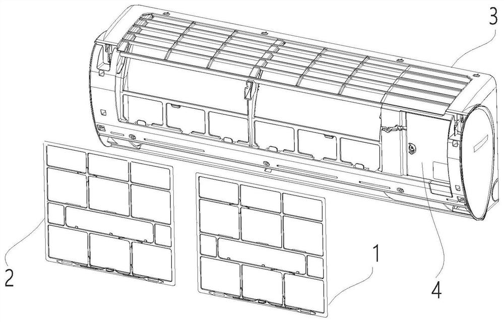
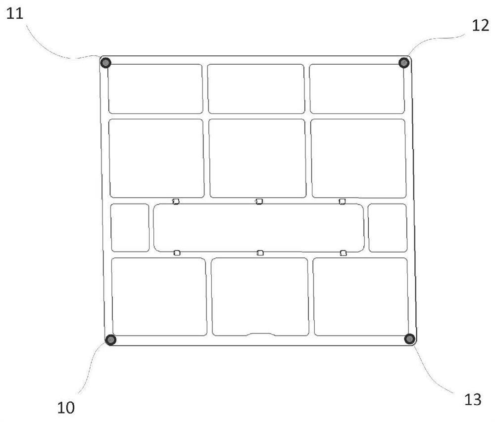
The invention belongs to the field of air conditioners, and particularly relates to an air conditioner indoor unit and a filter screen filth blockage detection method thereof. The air conditioner indoor unit comprises a shell, at least one pressure sensor assembly and a controller; an air inlet is formed in the shell, a mounting groove is formed in the air inlet, and a filter screen is mounted onthe mounting groove; the at least one pressure sensor assembly is arranged on the contact surface of the filter screen and a filter tank and is used for detecting and sending the pressure value of thefilter screen in the mounting tank; and the controller is located in the shell and used for receiving the pressure value detected by the pressure sensor assemblies and judging the filth blockage condition and/or the installation condition of the filter screen according to the detection result. The air conditioner indoor unit can accurately detect the filth blockage condition of the air conditioner filter screen, and is simple in structure and low in cost.

Description

technical field [0001] The invention belongs to the field of air conditioners, and in particular relates to a method for detecting dirty and clogged air conditioner indoor units and filter screens. Background technique [0002] The air conditioning system continuously exchanges heat with the indoor circulating air through the indoor unit heat exchanger to realize the control of the indoor air temperature and humidity adjustment. Because the air often contains suspended matter such as hair and dust, a filter is installed inside the air conditioner to filter air impurities, so as to avoid the heat exchanger from being blocked and affecting the heat exchange efficiency of the heat exchanger. During the long-term use of the air conditioner, it is inevitable that the filter will accumulate thick dust. If the degree of dirt and blockage is serious, on the one hand, the air output and heat exchange rate of the air conditioner will be reduced, and the performance of the air conditio...

Claims


Application Information

Patent Timeline
Patent Type & Authority Applications(China)
IPC IPC(8): F24F1/0073F24F11/39F24F11/89F24F11/64F24F11/61F24F11/52F24F140/10
CPCF24F11/39F24F11/52F24F11/61F24F11/64F24F11/89F24F2140/10F24F1/0073
Inventor 梁之琦吴俊鸿廖敏翟振坤连彩云梁博田雅颂熊绍森徐耿彬王现林
Owner GREE ELECTRIC APPLIANCES INC
Why Eureka
Try Eureka