
Motor testing device and testing method

A technology for motor testing and the motor under test, applied in the direction of motor generator testing, measuring device casing, etc., can solve the problems of cumbersome test operation methods, inconvenient testing work, and many complicated steps, so as to protect less or no damage, Simple structure and simple test steps

Pending Publication Date: 2020-09-25
中科灵动航空科技成都有限公司
View PDF0 Cites 0 Cited by
  • Summary
  • Abstract
  • Description
  • Claims
  • Application Information

AI Technical Summary

Problems solved by technology

[0003] In the process of realizing the present invention, the inventor found that there are at least the following problems in the prior art: in the traditional motor test, the test operation method is cumbersome, and there are many complicated steps, and the error rate is extremely high. Obtain various technical parameters of the product. In addition, due to the rich types of existing motors and many size series, it is necessary to use a variety of experimental devices with different specifications when testing different motors, which not only increases the cost, but also brings difficulties to the testing work. inconvenient

Method used


Image

  • Motor testing device and testing method
  • Motor testing device and testing method
  • Motor testing device and testing method

Examples


Embodiment 1

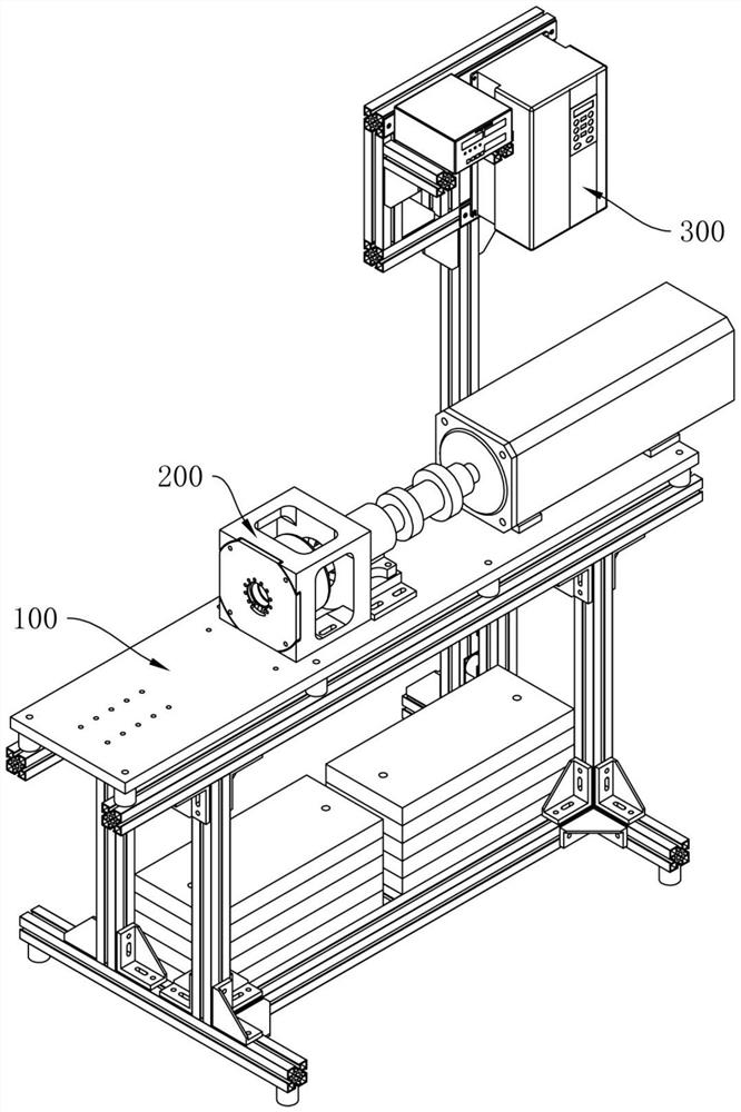
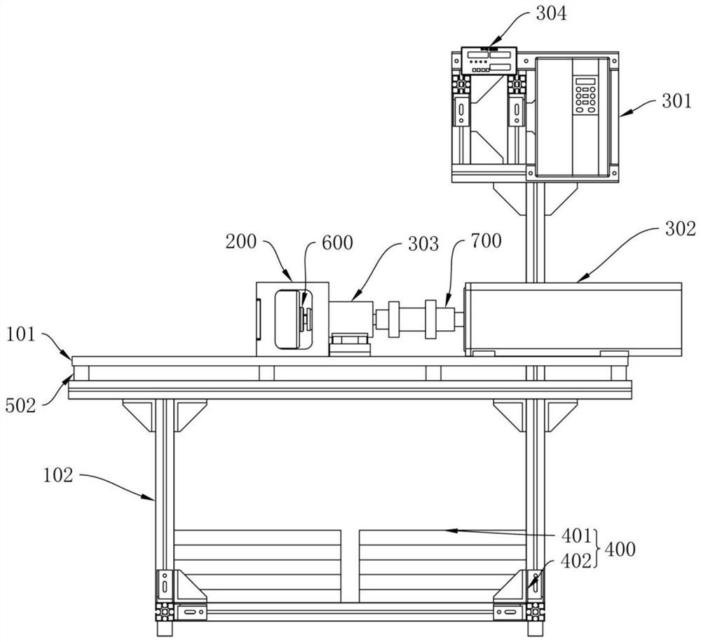
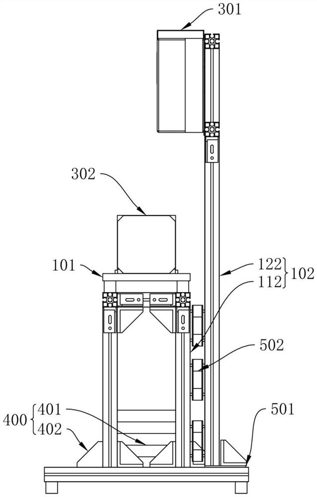
[0046] see Figure 1 to Figure 8 . A motor testing device described in this embodiment includes:

[0047] The base 100 is used to support the whole of the device, and the base 100 is used for the installation and connection of various components. In this embodiment, the base 100 is the outer frame of the support device as a whole, and the base 100 is used as a carrier. The connection and installation are all based on the base 100;

[0048] The first fixing assembly 200 is used for fixing the motor under test. The first fixing assembly 200 is arranged on the base 100. The first fixing assembly 200 has many different types. The size of the required first fixing assembly 200 is selected. In this embodiment, the first fixing assembly 200 has four types: a, b, c, and d. The a-type first fixing assembly can fix a large motor. The b-type first fixing component can fix large and medium-sized motors, the c-type first fixing component can fix medium-sized motors, and the d-type first...

Embodiment 2

[0059] see Figure 1 to Figure 8 . A motor testing method described in this embodiment uses the motor testing device described in Embodiment 1 for testing. Since the motor testing device has been described in detail in Embodiment 1, it will not be repeated in this embodiment. To repeat the same content, the motor test method includes the following steps:

[0060] Step 1: Fix the motor under test on the motor testing device through the first fixing component 200. Before performing this step, select a suitable first fixing component 200 according to the type and size of the motor, and then fix the motor under test;

[0061] Step 2: adjust the control unit 301, adjust the voltage and frequency of the output power supply, adjust the speed of the power unit 302, and drive the motor under test through the power unit 302;

[0062] Step 3: The detection unit 303 detects the motor under test, and converts the measured information into electrical signals and transmits them to the acqu...


PUM


Abstract

The invention discloses a motor testing device and testing method, and belongs to the field of motor testing. The objective of the invention is to reduce motor test operation steps, simplify a motor test flow and detect performance parameters including torque and rotating speed of a motor with high precision. According to the technical scheme, the motor testing device comprises a base used for supporting the whole device and used for installation and connection of all parts, a first fixing assembly used for fixing a tested motor and arranged on the base, and a testing assembly used for testingand data acquisition of the tested motor and arranged on the base.

Description

technical field [0001] The invention belongs to the field of motor testing, and relates to a motor testing device and a testing method. Background technique [0002] Motor refers to an electromagnetic device that converts or transmits electric energy according to the law of electromagnetic induction. Its main function is to generate driving torque as a power source for electrical appliances or various machines. After the motor is completed and repaired, the characteristic test of the drive motor and the performance test of the entire drive system are necessary for the analysis and control of the motor and drive system, so as to understand whether the motor can work normally and grasp the performance of the motor. [0003] In the process of realizing the present invention, the inventor found that there are at least the following problems in the prior art: in the traditional motor test, the test operation method is cumbersome, and there are many complicated steps, and the erro...

Claims


Application Information

Patent Timeline
Patent Type & Authority Applications(China)
IPC IPC(8): G01R31/34G01R1/04
CPCG01R1/04G01R31/34
Inventor 张代智梁虎杨超
Owner 中科灵动航空科技成都有限公司
Learn More