
Head-up display system and method with eye-tracking function

A head-up display system, eye tracking technology, applied in character and pattern recognition, instruments, computing, etc., can solve the problems of vehicle windshields that cannot be integrated with display devices, low energy utilization rate of infrared laser diodes, and low diffraction efficiency, etc. Achieve the effect of improving energy utilization, small size and high diffraction efficiency

Active Publication Date: 2022-06-03
BEIJING INSTITUTE OF TECHNOLOGYGY
View PDF9 Cites 0 Cited by
  • Summary
  • Abstract
  • Description
  • Claims
  • Application Information

AI Technical Summary

Problems solved by technology

However, this system is a wearable display device, and the display device cannot be integrated on the vehicle windshield, and the near-infrared holographic grating used for eye tracking is integrated with the visible light holographic grating used for HUD display through angle multiplexing. On the HUD film, there are problems of low diffraction efficiency and large volume
In addition, the energy utilization rate of the infrared laser diode is low and the energy consumption is large

Method used


Image

  • Head-up display system and method with eye-tracking function
  • Head-up display system and method with eye-tracking function
  • Head-up display system and method with eye-tracking function

Examples


Embodiment 1

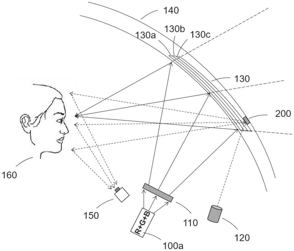
[0048] see figure 1 , which shows a head-up display system with eye tracking function, the system includes:

[0049] an image source 100a for generating a target image;

[0050] a diffuser screen 110 that receives the target image and scatters the target image to a grating combiner 130 described below;

[0051] a grating combiner 130 for diffracting the target image to the eyes of the user 160;

[0052] Near-infrared point light source 120 for emitting near-infrared light to the following near-infrared diffractive optical element 200;

[0053] a near-infrared diffractive optical element 200 for converting the near-infrared light into a scattered beam and diffracting it to the face or eyes of the user 160; and

[0054] The near-infrared detector 150 is used for receiving near-infrared images reflected from the face or eyes of the user 160 , and the near-infrared images are used to assist driving and / or adjust the spatial position of the target image diffracted to the eyes of t...

Embodiment approach

[0055] According to yet another preferred embodiment of the present invention, the image source 100a includes CRT, LCD, LED or DMD. Preferably, the diffusing screen 110 is frosted glass, frosted paper or a holographic screen. Preferably, the grating combiner 130 includes a holographic grating, a micro-nano grating or a diffraction grating. Preferably, the grating combiner 130 is independent of the windshield 140 or integrated with the windshield 140 .

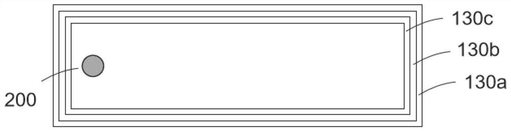
[0056] Preferably, the grating combiner 130 is a layered stack structure or a multiplex structure. Preferably, the near-infrared diffractive optical element 200 is square, circular, rectangular or trapezoidal.

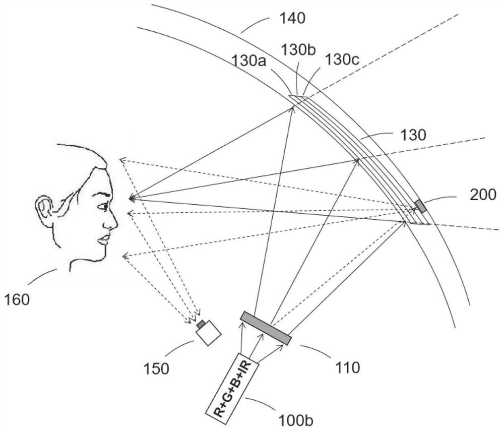
[0057] According to yet another preferred embodiment of the present invention, the near-infrared diffractive optical element 200 and the grating combiner 130 are integrated together or provided independently of each other. It can be understood that when the grating combiner 130 and the near-infrared diffractive optica...


PUM


Abstract

A head-up display system with eye tracking function is provided, which includes: an image source for generating a target image; a scattering screen for receiving the target image and scattering the target image to the following grating combiner; the grating combiner, It is used to diffract the target image to the user's eyes; a near-infrared point light source is used to emit near-infrared light to the following near-infrared diffractive optical element; a near-infrared diffractive optical element is used to convert the near-infrared light into a scattered beam Diffraction to the user's face or eyes; and a near-infrared detector for receiving the near-infrared image reflected by the user's face or eyes, which is used to assist driving and / or adjust the target image diffracted to the user's eyes Spatial location. The system has high diffraction efficiency, small size, high energy utilization rate of near-infrared point light source, and can reduce power consumption.

Description

technical field [0001] The invention relates to a head-up display system and method with an eye-tracking function, belonging to the technical field of display. Background technique [0002] Head Up Display (HUD) for short, also known as head-up display system, is a technology that projects various vehicle information and navigation information outside the windshield. [0003] Advanced driver assistance systems (ADAS) in the field of in-vehicle head-up displays have become a new research hotspot. The commonly used technical means in advanced driver assistance systems are eye tracking technology or driver tracking technology, which provides real-time information feedback to the vehicle driver by identifying the near-infrared image reflected by the driver's face or eyes. [0004] For example, patent US20160150218A1 discloses a combined structure for a head-up display (HUD) system and a driver monitoring system, the combined structure includes: a HUD system including a first re...

Claims


Application Information

Patent Timeline
Patent Type & Authority Patents(China)
IPC IPC(8): G02B27/01G02B27/00G06V40/16G06V20/59
CPCG02B27/0101G02B27/0093G06V40/18G06V20/597
Inventor 刘娟吕振律
Owner BEIJING INSTITUTE OF TECHNOLOGYGY
Learn More