[0021] In order to facilitate the understanding of the present invention, the present invention will be described more fully below with reference to the relevant drawings. The drawings show typical embodiments of the invention. However, the present invention can be implemented in many different forms and is not limited to the embodiments described herein. On the contrary, the purpose of providing these embodiments is to make the disclosure of the present invention more thorough and comprehensive. It should be understood that the embodiments of the present invention and the specific features in the embodiments are detailed descriptions of the technical solutions of the present application, rather than limitations on the technical solutions of the present application. In the case of no conflict, the embodiments of the present invention and the technical features in the embodiments Can be combined with each other.
[0022] It should be noted that when an element is referred to as being "fixed to" another element, it can be directly on the other element or a central element may also exist. When an element is considered to be "connected" to another element, it can be directly connected to the other element or an intermediate element may be present at the same time. The terms "front", "rear" and similar expressions used herein are for illustrative purposes only.
[0023] Unless otherwise defined, all technical and scientific terms used herein have the same meaning as commonly understood by those skilled in the technical field of the present invention. The terminology used in the specification of the present invention herein is only for the purpose of describing specific embodiments, and is not intended to limit the present invention.
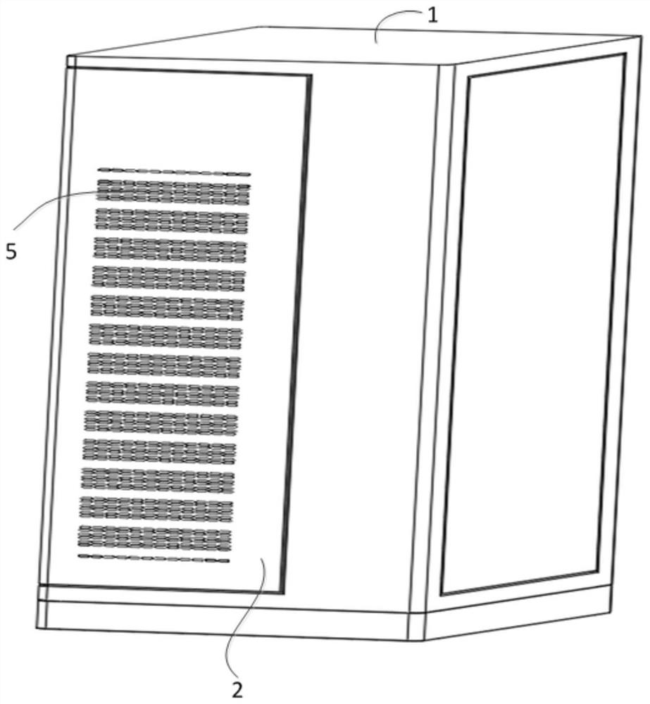
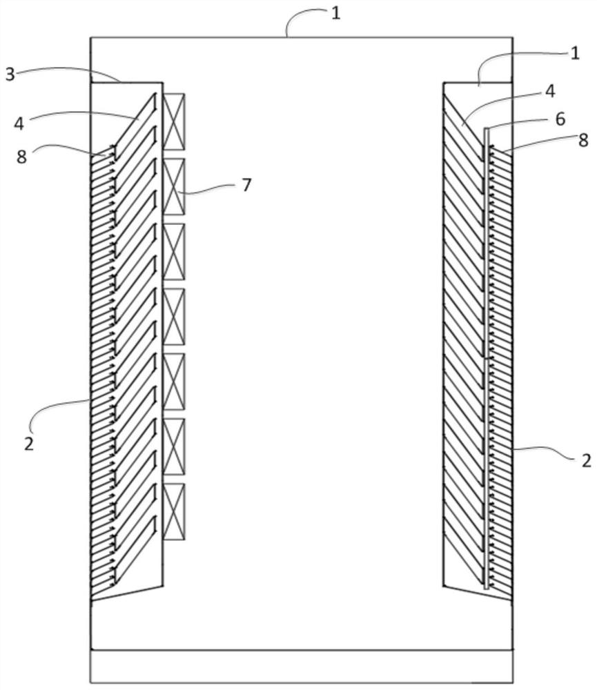
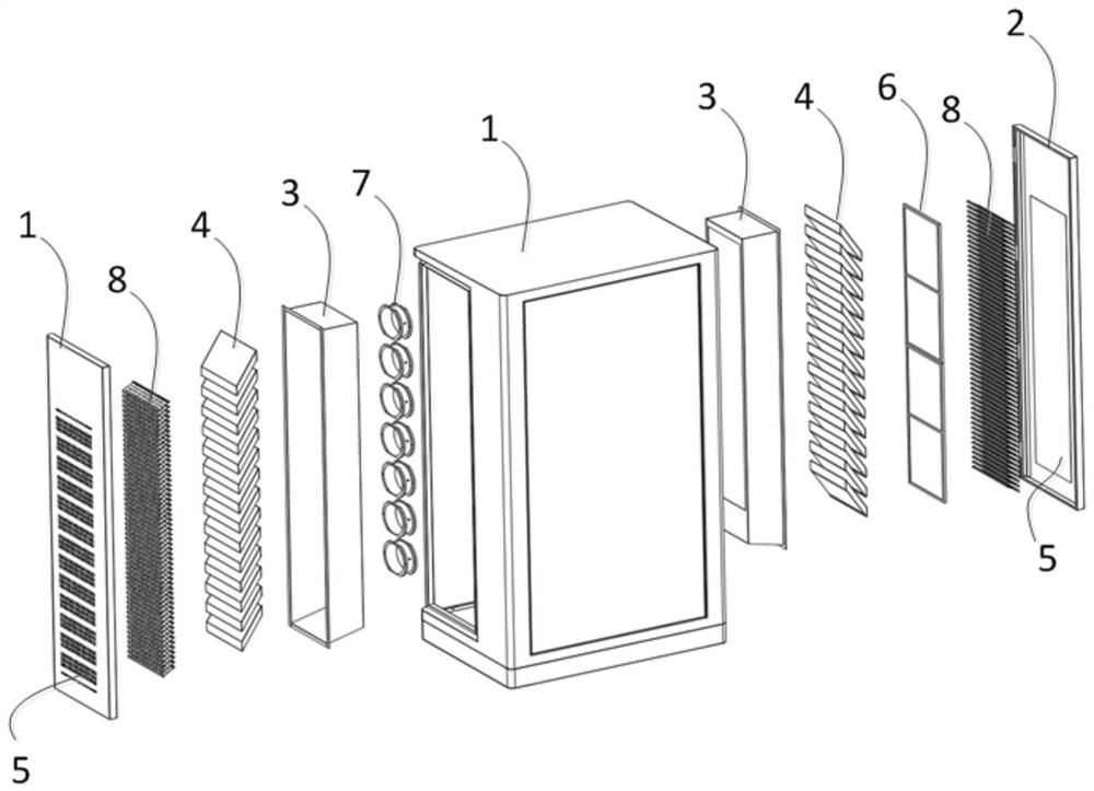
[0024] reference Figure 1-3 The outdoor charging pile of the present invention includes a cabinet 1 which includes an air inlet assembly and an air outlet assembly, and the air inlet assembly and the air outlet assembly are arranged oppositely.
[0025] The air inlet component and the air outlet component both include a fairing 3, a ventilation movable door 2, a waterproof shutter 8, an insect-proof steel wire mesh 5, and a row of waterproof sound-absorbing sheets 4. In addition, the air inlet assembly further includes a G4 dust-proof net 6, and the air outlet assembly further includes a plurality of fans 7.
[0026] Wherein, the fairing 3 is roughly a rectangular body with an opening at the front and a plurality of ventilation windows at the rear. The ventilation movable door 2 is arranged at the front opening of the fairing 3 and is rotatably connected with the fairing 3, so that the ventilation movable door 2 can be opened or closed, so as to facilitate the alignment of the fairing 3 Other internal structures are maintained. Specifically, in this embodiment, the welding assembly of the ventilation movable door 2 and the welding assembly of the fairing 3 are movably riveted.
[0027] Wherein, the waterproof louver 8 and the row of waterproof sound-absorbing sheets 4 are arranged in the fairing 3, the row of waterproof sound-absorbing sheets 4 is located behind the waterproof louver 8, and the row of waterproof sound-absorbing sheets 4 Arranged in an array along the height direction of the cabinet body 1, the waterproof sound-absorbing sheet 4 is specifically a rectangular plate-shaped structure made of sound-absorbing materials.
[0028] In this embodiment, the waterproof louver 8 is fixed to the fairing 3 by welding. For example, both sides of the waterproof louver 8 are welded to the two side walls of the fairing 3 and kept inclined.
[0029] In this embodiment, the multiple fans 7 of the air outlet assembly are arranged along the height direction of the cabinet 1, and are specifically installed on the welding assembly behind the fairing 3.
[0030] In this embodiment, such as figure 2 As shown, viewed from the front perspective of the fairing 3, the waterproof sound-absorbing sheet 4 and the waterproof louver 8 are both inclined upward, and the inclination angle of the waterproof sound-absorbing sheet 4 is greater than the inclination angle of the waterproof louver 8. For example, in this embodiment, the inclination angle of the waterproof louver 8 is 45 degrees, and the inclination angle of the waterproof sound-absorbing sheet 4 is 60 degrees.
[0031] reference image 3 The ventilation movable door 2 is provided with a plurality of ventilation windows, the plurality of ventilation windows are arranged in an array along the height direction of the cabinet 1, the ventilation windows are rectangular, and the length direction is perpendicular to the cabinet In the height direction of 1, the insect-proof steel wire mesh 5 is provided on the back of the air-permeable movable door 2, and the insect-resistant steel wire 5 covers the plurality of air-permeable windows. The insect-resistant steel wire 5 can be fixed to the air-permeable movable door 2 by welding.
[0032] reference figure 2 , 3 , The G4 dust-proof net 6 of the air intake assembly is arranged between the waterproof muffler sheet 4 and the waterproof shutter 8. The G4 dust-proof net 6 may be one piece or multiple pieces arranged along the height direction. Because the G4 dust-proof net 6 is installed in front of the waterproof muffler 4, the waterproof muffler 4 is free of dust maintenance, increases the service life of the waterproof muffler 4, reduces the maintenance workload, and solves the waterproof muffler 4 due to dust accumulation in the later waterproof muffler 4 Problems such as maintenance and replacement are needed to reduce the maintenance cost of the paper.
[0033] reference Figure 4-5 In consideration of the convenience of later maintenance, in this embodiment, the waterproof sound-absorbing sheet 4 and the G4 dust-proof net 6 on the air outlet side are preferably installed in a side pluggable manner. It can be understood that the waterproof sound-absorbing sheet 4 on the air inlet side can be fixed by welding, or it can be installed in a pluggable way on the side.
[0034] Specifically, refer to Figure 4 Taking the air outlet side as an example, the rear part of the fairing 3 has a row of fan installation positions 31, and the side wall of the fairing 3 is provided with a row of muffler installation openings 32 along the height direction. The inclination angle of the muffler installation openings 32 is based on the waterproof and sound-absorbing The required inclination angle of the piece 4 is opened. The row of waterproof sound-absorbing sheets 4 is inserted into the inside of the fairing 3 from the row of sound-proofing sheet installation openings 32 in a pluggable manner, and a waterproof pressure plate is detachably installed outside the side wall of the fairing 3 after insertion 9 to seal and waterproof the installation openings 32 of the row of silencers. Specifically, the waterproof pressing plate 9 adopts a sheet metal bending structure and a waterproof rubber strip matched with the periphery of the sheet metal bending structure to solve the problem of water leakage at the installation port 32 of the sound-absorbing sheet. The waterproof silencer 4 adopts side plugging and modularization, which solves the maintenance problem of the waterproof silencer 4 in the later stage, realizes simple maintenance and simple replacement of plugging and unplugging, reduces maintenance workload, and does not need to disassemble the fan 7 when maintaining the waterproof silencer 4 , Make maintenance simple and quick, reduce maintenance workload.
[0035] Specifically, refer to Figure 5 The other side wall of the fairing 3 is provided with a strip-shaped dust-proof net installation port 33, and the G4 dust-proof net 6 is inserted into the fairing 3 from the dust-proof net installation port 33 in a pluggable manner. Inside, and outside the side wall of the fairing 3 after insertion, a waterproof pressure plate 10 is detachably installed to seal and waterproof the dust-proof net installation port 33. The waterproof pressure plate 10 adopts a sheet metal bending structure and a waterproof rubber strip matched with the periphery of the sheet metal bending structure, so as to solve the problem of water leakage at the installation port 33 of the dust-proof net. The G4 dust-proof net 6 adopts side plugging and module realization It can solve the problem of the maintainability of the G4 dust filter in the later stage, realize the simple maintenance and simple replacement of the plug and unplug, and reduce the maintenance workload.
[0036] What needs to be said is that the waterproof silencer 4 and the G4 dust-proof net 6 can either be pluggable and installed on the two opposite side walls of the fairing 3, or can be pluggable on the same side wall of the fairing 3. Pull out the installation, if it is on the same side, you need the same waterproof plate.
[0037] It should be noted that the rear mentioned in this article refers to the side facing the inside of the cabinet 1.
[0038] In summary, the outdoor charging pile of the present invention has the following beneficial effects: In the present invention, the waterproof louver can achieve the waterproof effect, and the waterproof sound-absorbing sheet is located behind the waterproof louver. While achieving the sound-absorbing effect, the waterproof sound-absorbing sheet The inclination angle is greater than the inclination angle of the waterproof shutter, so the waterproof effect can be further improved. In short, the present invention can reduce noise while ensuring the waterproof effect. It not only meets the enclosure protection level IP55 but also reduces the noise of the system, so that the cabinet can meet the environmental noise daytime 3 Level requirements (65dB).
[0039] The embodiments of the present invention are described above with reference to the accompanying drawings, but the present invention is not limited to the above-mentioned specific embodiments. The above-mentioned specific embodiments are only illustrative and not restrictive. Those of ordinary skill in the art are Under the enlightenment of the present invention, many forms can be made without departing from the purpose of the present invention and the protection scope of the claims, and these are all within the protection of the present invention.