Oil cooling speed regulation type cooling system

A cooling system and speed regulation technology, applied in cooling/ventilation devices, casings/covers/supports, electrical components, etc., can solve the problems of cooling system temperature accumulation, lack of speed regulation function, etc., and achieve convenient speed regulation function , Simple structure, avoid the effect of temperature accumulation

Inactive Publication Date: 2020-09-25
NANJING MAGNET INTELLIGENCE TECH CO LTD
View PDF11 Cites 0 Cited by
  • Summary
  • Abstract
  • Description
  • Claims
  • Application Information

AI Technical Summary

Problems solved by technology

[0004] In view of the above situation, in order to overcome the defects of the prior art, the present invention provides an oil-cooled speed-adjustable cooling system, which effectively solves the problem of temperature accumulation caused by the cooling system, the formation of local hot spots, and the need to directly cool the heat source to improve the cooling efficiency. Problem with the speed control function

Method used


Image

  • Oil cooling speed regulation type cooling system
  • Oil cooling speed regulation type cooling system

Examples


Embodiment 1

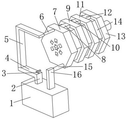
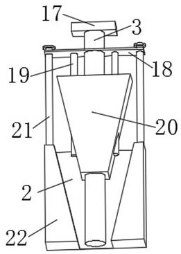
[0018] Embodiment one, by figure 1 and figure 2 Provided, the present invention includes a fuel tank 1, a first connecting pipe 2 is installed on the top side of the fuel tank 1, a second connecting pipe 4 is connected to the top of the first connecting pipe 2, a deflector 22 is fixed on the bottom of the first connecting pipe 2, and a deflector 22 is fixed on the bottom of the first connecting pipe 2. A screw rod 21 is installed on the top of the flow plate 22, the top of the screw rod 21 is connected with a top plate 18, a guide rod 19 is fixed on one side of the bottom end of the top plate 18, the middle part of the top plate 18 is sleeved with a rotating shaft 3, and the top of the rotating shaft 3 is fixed with a rotating rod 17, and the middle part of the rotating shaft 3 The outside is sleeved with a trapezoidal block 20, the top side of the second connecting pipe 4 is connected with a third connecting pipe 5, the top of the third connecting pipe 5 is fixed with an oil...

Embodiment 2

[0019] Embodiment two, on the basis of embodiment one, by figure 1 and figure 2 Given, a water pump is installed at the bottom of the oil tank 1 to provide sufficient oil pressure.

Embodiment 3

[0020] Embodiment three, on the basis of embodiment one, by figure 1 and figure 2 It is given that the two guide rods 19 are distributed symmetrically, which is convenient for uniform stress.


PUM


Abstract

The invention discloses an oil cooling speed regulation type cooling system which solves the problems of the cooling system that the temperature accumulation happens, the local hotspots are formed, aheat source needs to be directly cooled to improve the cooling efficiency, and a speed regulation function does not exists. The cooling system comprises an oil tank, a first connecting pipe is mountedat one side of the top end of the oil tank, and the top of the first connecting pipe is connected with a second connecting pipe. A guide plate is fixed at the bottom of the first connecting pipe, a screw is mounted at the top end of the guide plate, and a top plate is connected to top of the screw. A guide rod is fixed at one side of the top plate, a rotating shaft sleeves the middle of the top plate, and a rotating rod is fixed at the top of the rotating shaft. The middle of the rotating shaft is sleeved with a trapezoidal block, a third connecting pipe is connected to one side of the top ofthe second connecting pipe, an oil inlet pipe is fixed to the top of the third connecting pipe, and a base is mounted at one end of the oil inlet pipe away from the third connecting pipe. According to the invention, the temperature accumulation is avoided, the local hotspots are not formed, the heat source does not need to be directly cooled to improve the cooling efficiency, the structure is simple, and the cooling system has the speed regulation function and is convenient to use.

Description

technical field [0001] The invention belongs to the technical field of cooling, and in particular relates to an oil-cooling speed-regulating cooling system. Background technique [0002] Cooling refers to the process of reducing the temperature of a hot object without phase change. The motor casing needs to use a cooling system to reduce the temperature. The commonly used water cooling of the motor casing needs to click on the internal heat source to transfer to the outside through layers of materials, and then Taken away by the water channel, due to the existence of thermal resistance, there is a temperature gradient from the winding to the water-cooled casing, and the winding cannot be cooled directly, resulting in temperature accumulation and the formation of local hot spots, which will lead to abnormal use of the point casing temperature. [0003] However, the current cooling system causes temperature accumulation to form local hot spots and does not have the problem of ...

Claims


Application Information

Patent Timeline
Patent Type & Authority Applications(China)
IPC IPC(8): H02K9/19H02K5/20
CPCH02K5/20H02K9/19
Inventor 黄忠念
Owner NANJING MAGNET INTELLIGENCE TECH CO LTD
Why Eureka
Try Eureka