Self-regulation vegetation wall for ecological corridor construction

A self-regulating, corridor technology, applied in applications, plant protection, plant protection covers, etc., can solve problems such as water shortage and maintenance difficulties for plants

Inactive Publication Date: 2020-09-29
夏书梅
View PDF4 Cites 0 Cited by
  • Summary
  • Abstract
  • Description
  • Claims
  • Application Information

AI Technical Summary

Problems solved by technology

[0005] The purpose of the present invention is to provide a self-regulating vegetation wall for the construction of ecological corridors that can effectively maintain the growth of plants in view of the above-mentioned problems of water shortage and maintenance difficulties for plants

Method used


Image

  • Self-regulation vegetation wall for ecological corridor construction
  • Self-regulation vegetation wall for ecological corridor construction

Examples


Embodiment 1

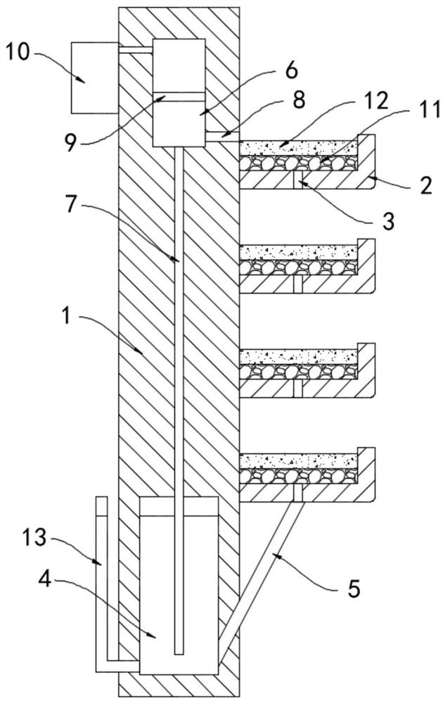
[0019] Such as figure 1 As shown, a self-regulating vegetation wall for ecological corridor construction includes a body of wall 1, and a plurality of plant grooves 2 are equidistantly installed from top to bottom on the side wall of the front side of the body of wall 1, and the bottoms of the plant grooves 2 are all opened. There are seepage holes 3, the inner bottom surface of the plant tank 2 is laid with a filter layer 11, the top of the filter layer 11 is laid with a planting layer 12, the wall 1 is provided with a water storage chamber 4, and the bottom of the plant tank 2 at the bottom is installed with a The seepage pipe 5 connected with the water storage chamber 4 and the filter layer 11 are made of stacked pebbles, which can filter the seepage rainwater and prevent the soil loss in the planting layer 12 from causing the blockage of the seepage pipe 5. There is an L-shaped transparent tube 13. The lower end of the L-shaped transparent tube 13 runs through the side wal...

Embodiment 2

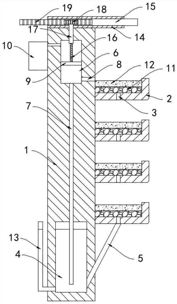
[0025] Such as figure 2 As shown, the difference between this embodiment and Embodiment 1 is that the sunshade device includes a chute 14 fixedly installed on the top of the wall 1, and a sunshade 15 is slidably connected in the chute 14, and the sunshade 15 is a grid plate. There is no need to worry about preventing rainwater from falling into the plant tank 2 in rainy days. The upper end of the sliding plug 9 is fixedly connected with a threaded rod 16, and the external thread of the threaded rod 16 is matched with a threaded barrel 17. The upper end of the threaded barrel 17 runs through the wall 1 and extends to Set in the chute 14, the upper end of the threaded cylinder 17 is coaxially equipped with a gear 18, and one end of the sun visor 15 is fixedly connected with a rack 19, and the gear 18 is meshed with the rack 19.

[0026] In this embodiment, at noon, the sunlight is relatively strong. At this time, the sliding plug 9 slides downward under the action of air pressu...


PUM


Abstract

The invention belongs to the field of ecological corridors, and particularly relates to a self-regulation vegetation wall for ecological corridor construction. The self-regulation vegetation wall comprises a wall body, wherein a plurality of plant grooves are equidistantly formed in the side wall of the front side of the wall body from top to bottom; seepage holes are formed in the bottoms of theplant grooves; a water storage cavity is formed in the wall body; a seepage pipe communicated with the water storage cavity is installed at the bottom of the lowermost plant groove; a water suction cavity is formed above the water storage cavity and communicates with the water storage cavity through a one-way water suction pipe; a one-way drainage pipe is arranged on the side wall of the water suction cavity, and the other end of the one-way drainage pipe extends into the corresponding plant groove; a horizontally-arranged sliding plug is connected into the water absorption cavity in a sealedand sliding mode; a light-transmitting box body is fixedly installed on the side wall of the rear side of the wall body; silver bromide particles are contained in the light-transmitting box body; andthe light-transmitting box body communicates with the water absorption cavity through an air pipe. Water can be intermittently supplied to plants, manual irrigation and maintenance are not needed, andconstruction of an ecological corridor is facilitated.

Description

technical field [0001] The invention belongs to the field of ecological corridors, in particular to a self-regulating vegetation wall for ecological corridor construction. Background technique [0002] Vegetation wall refers to the planting and cultivation of green plants on the original wall. It has the functions of beautifying the environment, reducing noise, purifying air, and adjusting temperature. It is widely used in gardens, parks, and ecological corridors. [0003] The traditional green vegetation wall has less soil for plants to grow on the wall and poor water storage capacity, and the wall is designed vertically to the ground, which is extremely inconvenient for manual watering, which is likely to cause problems such as plant death due to lack of water, and difficult maintenance. It is not conducive to the construction of ecological corridors. [0004] To this end, we propose a self-regulating vegetation wall for the construction of ecological corridors to solve t...

Claims


Application Information

Patent Timeline
IPC IPC(8): A01G9/02A01G13/02
CPCA01G9/025A01G13/0206
Inventor 夏书梅宋文海
Owner 夏书梅
Why Eureka
Try Eureka